Graco 210ES Repair Manual
Electric airless sprayer
Hide thumbs
Also See for 210ES:
- Operation manual (66 pages) ,
- Repair manual (37 pages) ,
- Operation (34 pages)
Table of Contents
Advertisement
Quick Links
Repair
190
/210
ES
Electric Airless Sprayer
- For portable spray application of architectural paints and coatings -
190
Model: 261825
ES
210
Model: 261830
ES
Maximum Working Pressure: 3000 psi (20.7 MPa, 207 bar)
Important Safety Instructions
Read all warnings and instructions in this manual.
Save these instructions.
Related Manuals
311988
311979
311995
English
Français
312015
Graco Inc. P.O. Box 1441 Minneapolis, MN 55440-1441
Copyright 2006, Graco Inc. is registered to I.S. EN ISO 9001
™
ES
311980
Español
311990 rev.B
ti9032a
Advertisement
Table of Contents

Related Manuals for Graco 210ES


Summary of Contents for Graco 210ES
- Page 1 Read all warnings and instructions in this manual. Save these instructions. Related Manuals 311988 311979 311995 311980 English Français Español 312015 ti9032a Graco Inc. P.O. Box 1441 Minneapolis, MN 55440-1441 Copyright 2006, Graco Inc. is registered to I.S. EN ISO 9001...
- Page 2 Warning Warning The following warnings are for the setup, use, grounding, maintenance and repair of this equipment. The exclamation point symbol alerts you to a general warning and the hazard symbol refers to procedure-specific risks. Refer back to these warnings. Additional, product-specific warnings may be found throughout the body of this manual where appli- cable.
- Page 3 Read fluid and solvent manufacturer’s warnings. For complete information about your material, request MSDS from distributor or retailer. • Check equipment daily. Repair or replace worn or damaged parts immediately with genuine Graco replacement parts only. • Do not alter or modify equipment.
-
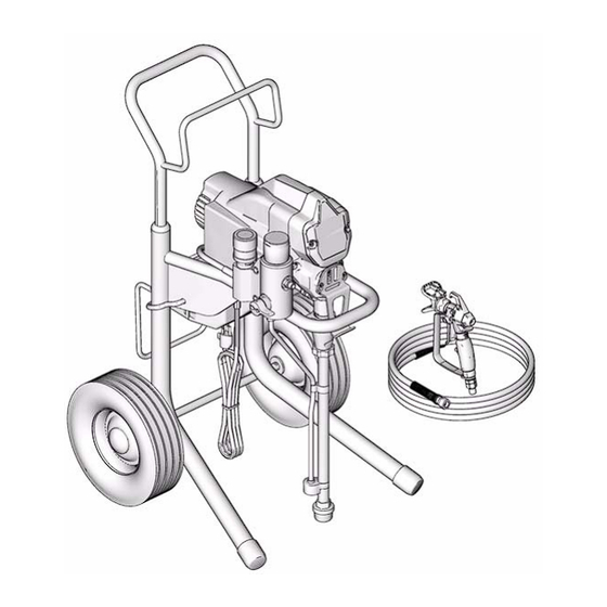
Page 4: Component Identification
Component Identification Component Identification ti9033a ti9034a Component Pressure Control ON/OFF Switch Power Cord Fluid Outlet Prime Valve Kick Stand (210 Pump Suction Tube Drain Hose Fluid Hose Guard Trigger Safety Lock Serial Number ID Label Filter Cap Pail Hook Power Flush Adapter Shutoff Valve 311990B... -
Page 5: Installation
Installation Installation Grounding and Electric Do not use the sprayer if the electrical cord has a dam- aged ground contact. Only use an extension cord with Requirements an undamaged ground contact. The sprayer cord includes a grounding wire with an appropriate grounding contact. -
Page 6: Pressure Relief Procedure
Pressure Relief Procedure Pressure Relief Procedure 3. Turn prime valve down. Follow this Pressure Relief Procedure whenever you are instructed to relieve pressure, stop spraying, check or service equipment or install or clean spray tip. ti8326a 1. Turn OFF power and turn pressure control to lowest pressure setting. -
Page 7: General Repair Information
General Repair Information General Repair Information To reduce risk of serious injury, including electric shock: • Do not touch moving or electric parts with fingers or tools while testing repair. • Unplug sprayer when power is not required for Flammable materials spilled on hot, bare, motor testing. -
Page 8: Troubleshooting
Troubleshooting Troubleshooting What To Check What To Do Problem (If check is OK, go to next check) (When check is not OK, refer to this column) Motor Won’t Operate Basic Fluid Pressure 1. Pressure control knob setting. Slowly increase pressure setting to see if motor Motor will not run if set at mini- starts. - Page 9 Troubleshooting What To Check What To Do Problem (If check is OK, go to next check) (When check is not OK, refer to this column) Basic Electrical 1. Electric supply. ON/OFF switch in Turn ON/OFF switch to ON position. Reset See wiring diagram, page OFF position.
- Page 10 Troubleshooting What To Check What To Do Problem (If check is OK, go to next check) (When check is not OK, refer to this column) Low Output 1. Worn spray tip. Relieve pressure, page 6. Replace tip. Refer to gun instruction manual, 311979. 2.
- Page 11 Troubleshooting What To Check What To Do Problem (If check is OK, go to next check) (When check is not OK, refer to this column) Motor runs and pump 1. Prime Valve Open. Close prime valve. strokes 2. Paint supply. Refill and reprime pump.
-
Page 12: Displacement Pump Replacement
Displacement Pump Replacement Displacement Pump Replacement See manual 312015 for pump repair instructions. 4. Cycle pump until pin (31) is in position to be removed. Removal 5. Disconnect power cord from outlet. 6. Push up retaining spring (C). Push out pump pin (31). 1. - Page 13 3. Install pump pin (31). Verify retainer spring (30a) is in groove over pump pin. ti9139a 9. Fill packing nut with Graco TSL until fluid flows onto top of seal. Install pail hanger (10 ) with screws (11). ti9144a 4. Push pump (33) up until pump threads engage.
-
Page 14: Drive Housing Replacement
Drive Housing Replacement Drive Housing Replacement Installation 1. Apply a liberal coat of grease to gears and needle bearing surfaces. Install thrust bearing (28) and gears (26) and (27) in motor front endbell. Removal 1. Relieve pressure, page 6. 2. Remove pump (33). Displacement Pump Replace- ment, page 12. - Page 15 Spin Test Spin Test Armature, Brushes, and Motor Wiring Open See Wiring Diagram, page 27. Circuit Test (Continuity) 1. Connect red and black motor leads with test lead. Turn motor fan by hand at about two revolutions per second. To check armature, motor winding and brush electrical 2.
-
Page 16: Fan Replacement
Fan Replacement Fan Replacement Removal Installation 1. Slide new fan (57a) on back of motor. Be sure fan blades face motor. 2. Install spring clip (57b). 1. Relieve pressure, page 6. Disconnect power cord from outlet. 3. Install shroud (12) with screw (13). 2. -
Page 17: Motor Brush Replacement
Motor Brush Replacement Motor Brush Replacement See Wiring Diagram, page 27. the brush lead. You will hear a snap when cap is securely in place. Removal 3. Strip approximately 1/4 inch (6 mm) of insulation Replace brushes worn to less than 1/4 in. (6 mm). from end of each yellow wire (C) from motor. -
Page 18: Control Board Replacement
Control Board Replacement Control Board Replacement See Wiring Diagram, page 27. 8. Pull control board out slightly and then slide control board back and off of frame. Make sure power cord is free and not wrapped around cord wrap. Removal 9. - Page 19 Control Board Replacement Installation 3. Slide control board into place on side of motor front endbell. 1. Push grommet and power cord wires into strain relief in control board (18). Strain Relief Grommet ti6122a 2. Connect power cord connectors to terminals indi- ti9154a cated on control board (18).
-
Page 20: Fuse Replacement
Fuse Replacement Fuse Replacement Removal 1. Relieve pressure, page 6. Disconnect power cord from outlet. 2. Remove kick stand (66) on 210 If the fuse is blown, check for: 3. Remove two screws (5) and toolbox (3). • Pinched or shorted wires 4. -
Page 21: Pressure Control Assembly Replacement
Pressure Control Assembly Replacement Pressure Control Assembly Replacement See Wiring Diagram, page 27. 7. Pull wires through hole (K). 8. Turn pressure control knob (17) counter clockwise as far as you can to access flats on either side of pressure control. Removal 9. - Page 22 Pressure Control Assembly Replacement Installation 3. Apply loctite to pressure control knob (B) threads. 4. Screw pressure control threads (B) into manifold and torque to 150 in-lb (17.0 N.m). Caution Be careful when tightening pressure control knob that wires are not pinched between pressure control and fluid manifold.
-
Page 23: Drain Valve Replacement
Drain Valve Replacement Drain Valve Replacement Installation 1. Install new seat gasket (44a) and valve seat (44b) on end of drain valve. 2. Screw drain valve (44) into filter manifold (43). Removal Torque to 120 to 130 in-lb. 1. Relieve pressure, page 6. Disconnect power cord 3. -
Page 24: Drain Line Replacement
Drain Line Replacement Drain Line Replacement Removal Installation 1. Cut drain line (49) from barbed fitting (51). 1. Screw barbed fitting (51) into filter manifold (43). 2. Unscrew barbed fitting from filter manifold (43). 2. Push drain line (49) onto barbed fitting. To make drain line more pliable and easier to install To reuse existing barbed fitting (51) and drain line over barbed fitting, heat end of drain line (49) with a... -
Page 25: Power Cord Replacement
Power Cord Replacement Power Cord Replacement See Wiring Diagram, page 27. Installation 1. Connect green ground wire (G) to frame with green ground screw (20). Be sure green ground wire ter- minal faces up or wires could get caught in shroud. Removal 2. -
Page 26: Motor Replacement
Motor Replacement Motor Replacement See Wiring Diagram, page 27. 7. Remove two screws (4) and filter manifold (43). 8. Remove green ground screw (20) and ground wire (G) from motor endbell. 9. Remove cover (14). Remove four screws (4) and motor (57) from frame (1). -
Page 27: 120V Wiring Diagram
120V Wiring Diagram 120V Wiring Diagram 311990B... - Page 28 Parts Parts 2 Ref 1 Ref 311990B...
-
Page 29: Parts List
Parts List Parts List Part Description Part Description 15J801 TUBE, suction, intake 288216 FRAME, cart, hi 103413 O-RING 245245 HANDLE, cart 115099 WASHER, garden hose 117493 SCREW, mach, hex washer hd 15J744 HOSE, cpld 109032 SCREW, mach, pnh 57❖ MOTOR, electric, 120V 192027 SLEEVE, cart 255157 190 ES;... -
Page 30: Parts Drawing
Parts Drawing Parts Drawing ti9159a Parts List Part Description Part Description 195811 LABEL, instruction 15K092 TUBE, drain 288503 TOOL BOX, assembly 244035 DEFLECTOR, barbed 117493 SCREW, mach, hex washer hd M70809 FITTING, barbed, hose 117501 SCREW, mach, slot hex wash hd 104361 O-RING 255169 CONTROL, pressure, 120V;... -
Page 31: Warranty
With the exception of any special, extended, or limited warranty published by Graco, Graco will, for a period of twelve months from the date of sale, repair or replace any part of the equipment determined by Graco to be defective. - Page 32 Warranty TO PLACE AN ORDER, contact your Graco distributor, or call 1-800-690-2894 to identify the nearest distributor. All written and visual data contained in this document reflects the latest product information available at the time of publication. Graco reserves the right to make changes at any time without notice.
Need help?
Do you have a question about the 210ES and is the answer not in the manual?
Questions and answers
How to remove filter csp
To remove the filter on a Graco 210ES:
1. Remove the filter from the gun if installed.
2. Clean and inspect the filter.
3. If flushing with water, flush again with mineral spirits or use Pump Armor to leave a protective coating.
4. Install the filter back after cleaning and inspection.
This answer is automatically generated