Table of Contents
Advertisement
Quick Links
TMG Corporate Website
Disclaimer:
All trademarks appearing within this PDF are trademarks of their respective owners.
Form 080/01
Complimentary Reference Material
This PDF has been made available as a complimentary service for you to assist in
evaluating this model for your testing requirements.
TMG offers a wide range of test equipment solutions, from renting short to long
term, buying refurbished and purchasing new. Financing options, such as
Financial Rental, and Leasing are also available on application.
TMG will assist if you are unsure whether this model will suit your requirements.
Call TMG if you need to organise repair and/or calibrate your unit.
If you click on the "Click-to-Call" logo below, you can all us for FREE!
TMG Products Website
Advertisement
Table of Contents

Related Manuals for Tektronix AMT75


Summary of Contents for Tektronix AMT75
- Page 1 Complimentary Reference Material This PDF has been made available as a complimentary service for you to assist in evaluating this model for your testing requirements. TMG offers a wide range of test equipment solutions, from renting short to long term, buying refurbished and purchasing new. Financing options, such as Financial Rental, and Leasing are also available on application.
- Page 2 Instructions AMT75 75 to 50 Ohm Impedance Adapter 070-9479-00 There are no current European directives that apply to this product. This product provides cable and test lead connections to a test object of electronic measuring and test equipment.
- Page 3 Copyright Tektronix, Inc. All rights reserved. Tektronix products are covered by U.S. and foreign patents, issued and pending. Information in this publication supercedes that in all previously published material. Specifications and price change privileges reserved. Printed in the U.S.A. Tektronix, Inc., P.O. Box 1000, Wilsonville, OR 97070–1000...
-
Page 4: Warranty
Tektronix, with shipping charges prepaid. Tektronix shall pay for the return of the product to Customer if the shipment is to a location within the country in which the Tektronix service center is located. Customer shall be responsible for paying all shipping charges, duties, taxes, and any other charges for products returned to any other locations. - Page 5 Eliminates unexpected service expenses For Information and Ordering For more information or to order Service Assurance, contact your Tektronix representative and provide the information below. Service Assurance may not be available in locations outside the United States of America. Name...
-
Page 6: General Safety Summary
Terms in this Manual. These terms may appear in this manual: WARNING. Warning statements identify conditions or practices that could result in injury or loss of life. CAUTION. Caution statements identify conditions or practices that could result in damage to this product or other property. AMT75 Impedance Adapter Instructions... -
Page 7: Contacting Tektronix
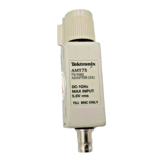
For product support outside of North America, contact your local Tektronix distributor or sales office. Service Contact your local Tektronix distributor or sales office. Or visit Support our web site for a listing of worldwide service locations. http://www.tek.com For other... - Page 8 (voltage standing-wave ratio). The adapter allows you to connect video and communication signals from a 75 coax cable to the 50 input of an oscillo- scope while minimizing aberrations and reflections. The AMT75 adapter fully complies with ANSI T1.102 and ITU-T G.703 input TekProbe output Figure 1: AMT75 Adapter CAUTION.
-
Page 9: Oscilloscope Connections
AMT75 Impedance Adapter Oscilloscope Connections As shown in Figure 2a, the output of the AMT75 adapter connects directly to the TekProbe II interface on Tektronix TDS Series oscilloscopes. With the addition of optional accessories, the AMT75 adapter connects to any instrument with a BNC or 50 SMA input. - Page 10 Input signal connections 50 TekProbe output Impedance Standard Data Rate (Mb/s) AMT75 DS-3 44.736 DS-4 139.264 STS-1 51.84 STS-3/STM-1 155.51 8.448 BNC Input 34.368 139.264 BNC Male to BNC Male Figure 2: Connecting the AMT75 adapter AMT75 Impedance Adapter Instructions...
-
Page 11: Specifications
AMT75 Impedance Adapter Specifications This section contains the specifications and compliances for the AMT75 Impedance Adapter. All specifications are guaranteed unless noted as “typical.” Typical specifications are provided for your convenience but are not guaranteed. Specifications that are marked with the symbol are checked in the Perfor- mance Verification on page 8. - Page 12 AMT75 Impedance Adapter 1.100 1.090 1.080 1.070 1.060 VSWR 1.050 Return 1.040 loss (dB) 1.030 1.020 1.010 1.000 1000 Frequency (MHz) Figure 3: Typical VSWR and return loss AMT75 Impedance Adapter Instructions...
-
Page 13: Performance Verification
Use the following procedures to verify the warranted specifications of the AMT75 adapter. Before beginning these procedures, photocopy the test record on page 13 and use it to record the performance test results for your AMT75 adapter. The recommended calibration interval is one year. -
Page 14: Output Impedance
4 Wire Range 2. Connect the AMT75 adapter as shown in Figure 4. NOTE. Connect the input and sense of the DMM to the output of the AMT75 adapter with a 50 BNC T adapter, two 50 BNC cables, and two BNC banana adapters. -
Page 15: Input Impedance
Performance Verification Input Impedance 1. Connect the AMT75 adapter as shown in Figure 5. CAUTION. To avoid damaging the 75 input, use only 75 connectors and cables on the 75 input. Multimeter 75.000 termination BNC adapter BNC cables and 75... -
Page 16: Attenuation Accuracy
3. Activate the power supply and adjust the output until the DMM reads 1.000 V. 4. Deactivate the power supply but do not change the output setting. 5. Connect the equipment as shown in Figure 7. AMT75 Impedance Adapter Instructions... - Page 17 6. Change the DMM range as follows: Setting Range 7. Activate the power supply. 8. Check that the voltage is attenuated by 5X 1.5% (the DMM reads 0.197 to 0.203). 9. Deactivate the power supply and disconnect the test setup. AMT75 Impedance Adapter Instructions...
- Page 18 __________ 76.125 Attenuation accuracy: 5X (–14 dB) 1.5% (measured with 2.500 V on the input) Input voltage 1.000 1.000 Output voltage 0.197 __________ __________ 0.203 Input output = attenuation factor 4.925 = __________ = __________ 5.075 AMT75 Impedance Adapter Instructions...
-
Page 19: Replaceable Parts
Replaceable Parts NOTE: Parts illustrated with dashed lines are not replaceable Figure 8: Replaceable parts AMT75 Impedance Adapter Instructions... - Page 20 Performance Verification Figure 9: Optional accessories AMT75 Impedance Adapter Instructions...
- Page 21 80009 TEKTRONIX INC 14150 SW KARL BRAUN DR BEAVERTON, OR 97077–0001 PO BOX 500 TK2548 XEROX CORPORATION 14181 SW MILLIKAN WAY BEAVERTON, OR 97005 TK2565 VISION PLASTICS INC 26000 SW PARKWAY CENTER DRIVE WILSONVILLE, OR 97070 AMT75 Impedance Adapter Instructions...
Need help?
Do you have a question about the AMT75 and is the answer not in the manual?
Questions and answers