Table of Contents
Advertisement
Quick Links
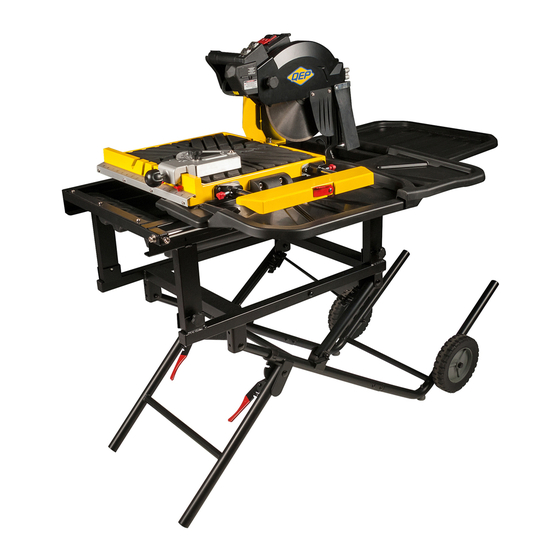
900 XT PRO TILE SAW
10
in.
OWNER'S MANUAL
254
mm
SCIE À CARREAUX PRO
MANUEL D'UTILISATION
SIERRA ELÉCTRICA PROFESIONAL
MANUAL DE OPERACIÓN
For Instructions in french and spanish,
please go to www.qep.com
Pour des instructions en français et en
espagnol, s'il vous plaît aller à www.qep.com
Para instrucciones en francés y en español,
por favor vaya a www.qep.com
OPERATING INSTRUCTIONS BEFORE USING THIS SAW.
DE SÉCURITÉ ET D'OPÉRATION AVANT D'UTILISER CETTE SCIE.
DE FUNCIONAMIENTO Y SEGURIDAD ANTES DE USAR ESTA SIERRA.
READ AND FOLLOW ALL SAFETY AND
LIRE ET SUIVRE TOUTES LES DIRECTIVES
LEA Y SIGA TODAS LAS INSTRUCCIONES
1
61900Q
Advertisement
Table of Contents

Subscribe to Our Youtube Channel
Related Manuals for QEP 900 XT PRO


Summary of Contents for QEP 900 XT PRO
- Page 1 For Instructions in french and spanish, please go to www.qep.com Pour des instructions en français et en espagnol, s’il vous plaît aller à www.qep.com Para instrucciones en francés y en español, por favor vaya a www.qep.com READ AND FOLLOW ALL SAFETY AND OPERATING INSTRUCTIONS BEFORE USING THIS SAW.
-
Page 2: Table Of Contents
TABLe OF CONTeNTS SECTION PAGE Product SPecificationS........................caLifornia ProPoSition 65......................... Safety GuideLineS - definitionS ...................... PoWer tooL Safety ..........................tiLe SaW Safety ............................. eLectricaL reQuireMentS and Safety..................tooLS needed for aSSeMBLy......................carton contentS..........................KnoW your tiLe SaW..........................aSSeMBLy and adJuStMentS......................oPeration.............................. -
Page 3: Safety Guidelines - Definitions
SAFeTY GUIDeLINeS - DeFINITIONS WARNING ICONS Your power tool and its Instruction Manual may contain "WArNING ICONS" (a picture symbol intended to alert you to and/or instruct you how to avoid a potentially hazardous condition). Understanding and heeding these symbols will help you operate your tool better and safer. Shown below are some of the symbols you may see. SAFeTY ALerT: Precautions that involve your safety. -
Page 4: Power Tool Safety
pOWer TOOL SAFeTY Z87.1. everyday eyeglasses have only impact– GeNerAL SAFeTY INSTrUCTIONS resistant lenses. they ARE NOT safety glasses. BeFOre USING THIS pOWer TOOL NOTE: Glasses or goggles not in compliance with Safety is a combination of common sense, staying alert anSi Z87.1 could seriously injure you when they and knowing how to use your power tool. -
Page 5: Tile Saw Safety
TILe SAW SAFeTY 12. ALWAYS USe IN WeLL-VeNTILATeD AreA. BeFOre USING THe WeT TILe SAW remove dust frequently. clean out dust from the WARNING interior of the saw to prevent a potential fire hazard. DO NOT OperATe YOUr WeT TILe SAW UNTIL 13. - Page 6 eLeCTrICAL reQUIreMeNTS AND SAFeTY use a separate electrical circuit for your tool. this circuit pOWer SUppLY AND MOTOr SpeCIFICATIONS must not be less than #14 wire and should be protected with a 15 amp time delay fuse. Before connecting the WARNING motor to the power line, make sure the switch is in the To avoid electrical hazards, fire hazards, or damage...
-
Page 7: Electrical Requirements And Safety
the adapter (fig. 2) has a rigid lug extending from it that Fig. 3 MuSt be connected to a permanent earth ground, such as a properly grounded receptacle box. CAUTION in all cases, make certain the receptacle is properly grounded. If you are not sure, have a qualified electrician check the receptacle. -
Page 8: Tools Needed For Assembly
TOOLS NeeDeD FOr ASSeMBLY CARTON CONTENTS Supplied Not Supplied UNpACKING AND CHeCKING CONTeNTS carefully unpack the tile saw and all its parts, and compare against the list below and the illustration on the next page. With the help of an assistant place the saw flat bladed screwdriver on a secure surface and examine it carefully. - Page 9 UNpACKING YOUr JOBSITe TILe SAW...
-
Page 10: Know Your Tile Saw
KNOW YOUr JOBSITe TILe SAW diamond blade rear anti-splash guard Power cord clamps on/off switch Wrench storage rear water catch Motor support arm tray cutting table assembly Side anti-splash guard Side Water catch tray (B) Blade wrench universal wrench Wheel Stand Side Water catch tray (a) Motor... -
Page 11: Assembly And Adjustments
ASSeMBLY AND ADJUSTMeNTS Fig. A WARNING For your safety, never connect plug to power source receptacle until all assembly and adjustment steps are complete, and you have read and understood the safety instructions. ASSeMBLING THe STAND (FIG. A) • unpack all parts, and group them together by type and size. - Page 12 FOLDING THe STAND (FIG. C, D, G) WARNING WARNING For your safety, never connect plug to power source receptacle until all assembly and adjustment steps read all instructions on the manual and labels are complete, and you have read and understood before operating the stand.
- Page 13 • Press the arbor lock button (8) on the motor under ASSeMBLING THe MOTOr SUppOrT ArM (FIG. H) • install the motor support arm onto base frame. thread the handle, holding it in firmly. (Fig. L) • the two bolts (from bag e) into the side holes of the Loosen the arbor bolt (3) and take the arbor bolt and motor support arm.
- Page 14 Side anti-splash guard (Fig. N) INSTALLING THe reAr WATer TrAY (FIG. Q, Q-1) • attached the side anti-splash guard (1) on the blade • align two slots located on the rear left and right ends cover. of the base frame with the arms of the rear water • thread two supplied screws (Bag "e") and tighten catch tray and gently push in.
- Page 15 Fig. r WARNING To prevent personal injury: • Always disconnect plug from the power source when making any adjustments. • This adjustment must be correct or accurate cuts can not be made. Also inaccurate adjustment can result serious personal injury. TrUING (SQUArING) THe CUTTING BLADe (FIG.
- Page 16 Adjusting the cutting blade 45° to cutting table (Fig. V) CUTTING BLADe DepTH (FIG. W) • • disconnect the saw from the power source. Loosen the blade elevation locking knob (1). • • Loosen the blade tilting locking knob (1) and move adjust the cutting head down until the outer rim of the cutting blade to the maximum bevel position, the cutting blade is at least 3/16 in.
- Page 17 THe LASer GUIDe (FIG. Y) AVOID DIreCT eYe CONTACT WARNING WARNING For your own safety, never connect the plug to a • Laser radiated when laser guide is turned on. power source outlet until all the adjustment Avoid direct eye contact. Always un-plug the steps are complete and you have read and tile saw from power source before making any understood the safety and operational instructions.
- Page 18 Procedure c (fig. BB, ee) LASer GUIDe ADJUSTMeNT (FIG. BB, CC, DD, ee) NOTE: all the adjustments for the operation of this NOTE: The pattern line should flush with the left side of machine have been completed at the factory. due to the cutting line.
-
Page 19: Operation
OPERATION • if the switch key is removed while the saw is BeFOre USING THe TILe SAW running, it can be turned "off" but cannot be WARNING restarted without inserting the switch key. To avoid mistakes that could cause serious, Fig. - Page 20 rAISe THe CUTTING HeAD (FIG. HH) Fig. JJ NOTE: always turn off when raising or pressing down the cutting head. • Loosen the blade elevation locking knob (1). • Lift the handle (2) upward to raise the cutting head. • When adjusting the cutting head to the desired height, tighten the blade elevation locking knob (1) to lock.
- Page 21 USING THe eXTeNSION TABLe, FOr SUppOrTING Fig. MM LArGe FOrMAT TILe (FIG. LL) • Loosen the extension table locking knobs (1). • Pull the extension table (2) out to the desired position. tighten the extension table locking knobs (1). • the stop plate (3) is designed for repetitive cutting.
- Page 22 BeVeL (MITer) CUT (FIG. OO) Fig. pp • using a pencil or marker marks the area to be cut on tile. • Loosen the blade elevation locking knob (1) to raise the cutting head. then, tighten the blade elevation locking knob. •...
-
Page 23: Maintenance
MAINTENANCE CLEANING WARNING • insert the water pump into a bucket of clean water Do not service, clean or maintain the saw without and pump the water through the hose. first turning off the motor and unplugging the saw • turn off and unplug the saw from the power source. -
Page 24: Troubleshooting
TrOUBLeSHOOTING WARNING To avoid injury from accidental starting, always turn switch OFF and unplug the tool before moving, replacing the blade or making adjustments. PROBLEM PROBLEM CAUSE SUGGeSTeD COrreCTIVe ACTION Motor does not start. 1. Power cord is not plugged 1. -
Page 25: Parts List
PARTS LIST 61900Q 900 XT PRO TILE SAW... - Page 26 PARTS LIST PARTS LIST ORDER ONLY BY MODEL NUMBER AND PART NUMBER OrDer ONLY BY MODeL NUMBer AND pArT NUMBer I.D. Description Size Q'ty I.D. Description Size Q'ty 61900Q -1 CORD CLAMP 61900Q -64 HEX. SOC. HD. CAP SCREW M8*1.25-30 61900Q -2 HEX.
- Page 27 SCHeMATIC - TILe SAW...
- Page 28 PARTS LIST FOR STAND ORDER ONLY BY MODEL NUMBER AND PART NUMBER I.D. Description Size Q'ty I.D. Description Size Q'ty 61900Q -126 END CAP 61900Q -153 PLATE 61900Q -127 FOOT PAD 61900Q -154 SUPPORTING TUBE ASSEMBLY 61900Q -128 WING NUT M8*1.25-2B 61900Q -155 SUPPORTING TUBE ASSEMBLY...
- Page 29 SCHEMATIC - STAND...
- Page 30 NOTES...
- Page 31 NOTES...
- Page 32 Made in Taiwan Fabriqué en Taiwan Hecho en Taiwan Boca Raton, FL 33487 www.qep.com O0214-8326 2014/10 Printed in Taiwan...
Need help?
Do you have a question about the 900 XT PRO and is the answer not in the manual?
Questions and answers