Table of Contents
Advertisement
Available languages
Available languages
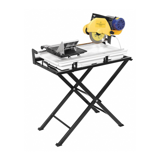
STK# 60010
18" Professional Tile Saw
by
OWNER'S MANUAL
Scie à Carreaux de 460mm
MANUEL D'UTILISATION
S i e rra Eléctrica Profesional de 460mm
MANUAL DE OPERACIÓN
LIMITED WARRANTY
Refer to warranty card.
GARANTIE LIMITÉE
Faire référence à la carte de guarantie.
GARANTIA LIMITADA
CAUTION!
Referirse a la tarjeta de guarantia.
Read and follow all safety
and operating instructions
before using this saw.
ATTENTION!
Lire et suivre toutes les directives
de sécurité et d'opération avant
d'utiliser cette scie.
¡AVISO!
Lea y siga todas las instrucciones de
funcionamiento y seguridad antes de
usar esta sierra.
Advertisement
Table of Contents

Related Manuals for QEP Brutus 60010


Summary of Contents for QEP Brutus 60010
- Page 1 STK# 60010 18" Professional Tile Saw OWNER’S MANUAL Scie à Carreaux de 460mm MANUEL D’UTILISATION S i e rra Eléctrica Profesional de 460mm MANUAL DE OPERACIÓN LIMITED WARRANTY Refer to warranty card. GARANTIE LIMITÉE Faire référence à la carte de guarantie.
-
Page 2: Table Of Contents
STK# 60010 18" Professional Tile Saw Scie à Carreaux de 460mm S i e rra Eléctrica Profesional de 460mm TABLE OF CONTENTS TABLE DES MATIÈRES CONTENIDO General Safety Instructions ........4 Directives Générales de Sécurité ......17 Instrucciones de Seguridad General ....30 Electrical Requirements ..........5... -
Page 3: General Safety Instructions
GENERAL SAFETY INSTRUCTIONS Read this owner's manual completely and make sure you understand all of it's safety guidelines. KEEP GUARDS IN PLACE and in working order. 15. MAINTAIN TOOLS WITH CARE. Keep tools clean and in good working condition for maximum safety REMOVE ADJUSTING KEYS &... -
Page 4: Electrical Requirements
GENERAL SAFETY (Cont.) 29. POSITIONING OF TILE SAW To avoid the possibility of the appliance plug NOTE: This tool is intended for use on a circuit that has an or receptacle getting wet, position the tile saw to one outlet that looks like the one illustrated in Fig 2 (B). The tool side of a wall-mounted receptacle to prevent water from has a grounding plug that looks like the plug illustrated in dripping onto the receptacle or plug. -
Page 5: Extension Cords
ELECTRICAL REQUIREMENTS (Cont.) • IMPROPER USE OF EXTENSION CORDS MAY NOTE: When using an extension cord, ensure all cords are CAUSE INEFFICIENT OPERATION OF YOUR TOOL, no smaller than #12 gauge, rated at a 20-amp minimum, which can result in overheating. Be sure your extension and equipped with 3-prong plugs. -
Page 6: Saw Features
INTRODUCTION We at Q.E.P. would like to congratulate you on selecting the 60010 Tile Saw. We are certain that you will be pleased with your purchase. QEP is the world’s largest supplier of flooring installation tools and accessories, and we takes pride in producing the finest tile saws in the industry. -
Page 7: Set Up And Operation
The 60010 requires minimal assembly, and as been factory inspected before shipping. Carefully open the container and remove all saw components and packing materials. Ensure that you have each item before discarding the container or packing materials. -
Page 8: Stand Assembly
STAND ASSEMBLY ATTACHING FRAME TO STAND If you are not using the folding stand, set the saw frame on a solid, flat workbench or table. Fig E1 Fig E2 To attach the Saw Frame to the Stand use the a s s e m b l y Fig D1 Fig D2 h a rd w a re (Fig. -
Page 9: Cutting Head Assembly
CUTTING HEAD ASSEMBLY Support Post Fig G4 Fig G3 Fig F1 Fig F2 Slide the Blade Guard over the support post on the motor assembly (Fig G3). Secure by tightening the provided To attach the Cutting Head (Fig F1), find the Motor adjustment knob (Fig G4). -
Page 10: Diamond Blade Installation
BLADE INSTALLATION (cont.) WATER PUMP INSTALLATION Blade Shaft Lock Fig H5 Fig H6 Fig K1 Fig K2 With one hand, press the Blade Shaft Lock. With the other, tighten the blade shaft nut (Fig H5). Release the Remove the water pump from its box and ensure that it is Blade Shaft Lock after the nut is tightened (Fig H6). -
Page 11: Water Pump Safety
CAUTION: ALWAYS TURN OFF SAW AND UNPLUG FROM POWER SOURCE BEFORE REMOVING BELT GUARD OR ADJUSTING/CHANGING BELT. The 60010 Tile Saw has (2) motor speeds: 3450 & 2450 RPM to enable the operator to cut or profile materials at the Fig L7 Fig L8 speed that is best suited for the application. -
Page 12: Cutting Depth
CUTTING DEPTH CUTTING OPERATION WARNING! Do not attempt to cut pieces too small. Avoid awkward hand positions where sudden slip could cause your hand or finger to come in contact with the diamond blade. When cutting any material, make sure that it is fully s u p p o rted. -
Page 13: 45 O Angle Cuts With Angle Guide
CUTTING OPERATION (cont.) SAW MAINTENANCE ANGLE CUTS WITH RIP GUIDE WARNING! Do not service, clean or maintain the saw without first turning off the motor and unplugging the saw from it's power source. Failure to do so may result in serious injury to the operator. -
Page 14: Blade Dressing
SAW MAINTENANCE (cont.) TROUBLESHOOTING BLADE DRESSING OVERHEATING OF SAW: After several uses, diamonds on the outer edge of the blade may become smoothed or “glazed” over. This will A. Turn saw off and let it rest until motor is cool to the touch. -
Page 16: Directives Générales De Sécurité
DIRECTIVES GÉNÉRALES DE SÉCURITÉ Lisez intégralement ce manuel du pro p r i é t a i re et assurez-vous de bien comprendre toutes les directives de sécurité. GARDEZ LES PROTÈGE-LAMES EN PLACE et en 15. MAINTENEZ LES OUTILS AVEC SOIN. Gardez les bon état de fonctionner. -
Page 17: Installations Électriques
DIRECTIVES DE SÉCURITÉ (Suite) 29. POSITIONNEMEN T DE L A SC I E À C A RR E AU X Afin d’éviter de mouiller la fiche de l’appareil ou NOTEZ: Cet outil est destiné à un usage sur un circuit avec de la prise, positionnez la scie à... -
Page 18: Cordons D'alimentation
INSTALLATIONS ÉLECTRIQUES (Suite) NOTEZ: Lorsque vous utilisez un cordon d’alimentation, • UNE MAUVAISE UTILISATION DE LA RALLONGE assurez-vous que tous les cordons ne sont pas plus petit PEUT C O MPROMET TR E L E BON FO N CTIONN EMENT que le calibre #12, nominal minimum de 20-amp, et DE VOTRE OUTIL et provoquer une surchauffe. -
Page 19: Caractéristiques De La Scie
INTRODUCTION Nous, chez Q.E.P., aimerions vous féliciter d’avoir choisi la scie à carreaux 60010. Nous sommes persuadés que votre achat saura vous plaire. QEP est le plus important fournisseur d’outils et d’accessoires d’installation de planchers et nous sommes fiers de fabriquer les meilleures scies à carreaux de l’industrie. Ce manuel du propriétaire contient l’information nécessaire pour faire fonctionner et entretenir votre nouvelle scie 60010 de... -
Page 20: Réglage Et Fonctionnement
La scie 60010 exige un minimum d’assemblage et elle a été inspectée à l’usine avant d’être expédiée. Ouvrez le conteneur avec soin et retirez toutes les composantes de la scie et le matériel d’emballage. Assurez-vous d’avoir toutes les pièces avant de jeter le conteneur et le matériel d’emballage. -
Page 21: Assemblage De L'établi
ASSEMBLAGE DE L’ÉTABLI ATTACHER LE CADRE À L’ÉTABLI Si vous n’utilisez pas l’établi pliable, ajustez le cadre de la scie sur une surface plane et solide ou sur une table. Illust. E1 Illust. E2 Pour attacher le cadre de la scie à l’établi, utilisez la Illust. -
Page 22: Assemblage De La Tête De Coupe
ASSEMBLAGE DE LA TÊTE DE COUPE Poteau de soutien Illust. G3 Illust. G4 Illust. F1 Illust. F2 Faites glisser le protège-lame par-dessus le poteau de soutien sur l’assemblage du moteur (Illust. G3). Fixez Pour attacher la tête de coupe (Illust. F1), trouvez l’arbre solidement en serrant bien la poignée de réglage fournie de support du moteur, inséré... -
Page 23: Installation Du Plateau Pour L'eau
I N S TA L L ATION DE LA LAME (Suite) I N S TA L L ATION DE LA POMPE À EAU Lame Arbre Verrou Illust. H5 Illust. H6 Illust. K1 Illust. K2 Avec une main, pressez sur le verrou de l’arbre de la lame. -
Page 24: Sécurité De La Pompe À Eau
P ROT È G E - C O U R RO I E , A J U STER OU CHANGER LA COURRO I E . La scie à carreaux 60010 possède un moteur à deux (2) vitesses : 3450 et 2450 T/M pour permettre à l’opérateur de Illust. -
Page 25: Profondeur De La Coupe
OPÉRATION DE COUPE PROFONDEUR DE LA COUPE MISE EN GARDE! N’essayez pas de couper des morceaux t rop petits. Éviter positionner mains maladroitement de manière à risquer que celles-ci ou vos doigts viennent en contact avec la lame diamantée. Lorsque vous coupez du matériel, assurez-vous qu’il est pleinement soutenu. -
Page 26: Coupes D'angle À 45° Avec Le Guide D'angles
OPÉRATION DE COUPE (Suite) ENTRETIEN DE LA SCIE COUPES D’ANGLE DE 45 AVEC LE MISE EN GARDE! Ne réparez pas, ne nettoyez pas et ne GUIDE DE FENTE faites pas l’entretien de la scie sans, au préalable, avoir fe rmé le moteur et l’avoir débra n ché de sa sourc e d’alimentation. -
Page 27: Alignement De La Lame
ENTRETIEN DE LA SCIE (Suite) DÉPANNAGE ALIGNEMENT DE LA LAME SURCHAUFFE DE LA SCIE: A. Arrêtez la scie et laissez le moteur reposer Après plusieurs utilisations, les diamants sur la bordure jusqu’à ce qu’il soit froid au toucher. extérieure de la scie peuvent devenir lisses ou "émaillés". B. -
Page 28: Liste Des Pièces
LISTE DES PIÈCES DIAGRAMME DES PIÈCES PostScript Picture 60010 Parts DiagramFR.eps - 29 -... -
Page 29: Instrucciones De Seguridad General
INSTRUCCIONES GENERALES DE SEGURIDAD Lea por completo este manual del propietario y asegúrese de que comprende todos los lineamientos de seguridad. MANTENGA LAS PROTECCIONES EN SU LUGAR 14. NO TRAT E A LC A N ZA R A LGO y operativas. ENCUENTRE DEMASIADO LEJANO. -
Page 30: Requisitos Eléctricos
INSTRUCCIONES DE SEGURIDAD (Cont.) 29. POS I CI ON AMI ENT O D E LA S IE RRA PA RA LO SE TA S Para evitar la posibilidad de que el enchufe de la NOTA : La sierra electrica professional esta diseñada para herramienta o el tomacorriente se mojen, coloque la ser conectada en un toma corriente empotrado y conectado sierra para losetas a un lado del tomacorriente... -
Page 31: Cables De Extensión
REQUISITOS ELECTRICOS (Cont.) • EL USO INCORRECTO DE LOS CABLES DE NOTA: Cuando se usa un cable de extencion asegurece de EXTENSIÓN PODRÍA PROVOCAR UN que sean mas pequeños que el clasificado como calibre RENDIMIENTO INEFICAZ DE LA HERRAMIENTA , #12 y un minimo de 20amp y equipado con un toma lo que podría provocar sobrecalentamiento. -
Page 32: Características De La Sierra
INTRODUCCION En Q.E.P. deseamos felicitarle por seleccionar la Sierra para losetas 60010. Estamos seguros de que quedará satisfecho con su compra. QEP es el proveedor más importante del mundo de herramientas para la instalación de pisos, y nos enorgullece producir las sierras para losetas de mayor calidad en la industria. -
Page 33: Configuración Y Operación
La 60010 requiere un ensamblaje mínimo; además, fue revisada en fábrica antes de enviarse. Abra cuidadosamente el envase y elimine todos los componentes y materiales de embalaje de la sierra. Asegúrese de contar con cada componente antes de desechar el empaque o los materiales de embalaje. -
Page 34: Ensamblaje Del Soporte
ENSAMBLAJE DEL SOPORTE SUJECION DEL ARMAZON AL SOPORTE Si no está usando un soporte plegable, coloque el arm a z ó n de la sierra sobre una mesa o banco de trabajo sólido y plano. Fig D1 Fig D2 Fig E1 Fig E2 El soporte de la sierra incluye 2 soportes cruzados para Para sujetar el Armazón de la Sierra al Soporte use los... -
Page 35: Ensamblaje Del Cabezal Cortador
ENSAMBLAJE DE LA CABEZA CORTADORA Poste de soporte Fig G3 Fig G4 Deslice la Protección de la cuchilla sobre el poste de Fig F1 Fig F2 soporte en el ensamblaje del motor (Fig. G3). Asegure ajustando la perilla de ajuste incluida (Fig. G4). Para sujetar la Cabeza cortadora (Fig. -
Page 36: Instalación De La Bandeja Para Agua
INSTALACION DE LA CUCHILLA (cont.) INSTALACION DE LA BOMBA DE AGUA Seguro del eje de la cuchilla Fig H5 Fig H6 Con una mano, presione el Seguro del eje de la cuchilla. Con la otra, ajuste la tuerca del eje de la cuchilla (Fig. H5). Fig K1 Fig K2 Libere el Seguro del eje de la cuchilla después de apretar... -
Page 37: Medidas De Seguridad Para La Bomba De Agua
DESENCHUFELA DE LA FUENTE DE ENERGIA ANTES DE QUITAR LA PROTECCION DE LA BANDA O AJUSTAR / CAMBIAR LA BANDA. La Sierra para losetas 60010 cuenta con (2) velocidades de motor: 3450 y 2450 RPM para permitir que el operador Fig L7 Fig L8 corte o perfile materiales a la velocidad más adecuada para... -
Page 38: Profundidad De Corte
PROFUNDIDAD DE CORTE OPERACION DURANTE EL CORT E ¡ADVERTENCIA! No intente cortar piezas muy pequeñas. Evite colocar las manos en posiciones inadecuadas en las que un movimiento súbito pudiese provocar que sus manos o dedos entrasen en contacto con la cuchilla de diamante. -
Page 39: Cortes De Inglete Con Bloque De Ingletes
OPERACION DE CORTE (cont.) MANTENIMIENTO DE LA SIERRA CORTES EN ANGULO DE 45° ¡ADVERTENCIA! No realice labores de mantenimiento, CON LA GUIA DE CORTE limpie o repare la sierra sin antes apagar el motor y desenchufar la sierra de la fuente de energía. No cumplir esta indicación podría provocar lesiones serias al operador. -
Page 40: Pulido De La Cuchilla
MANTENIMIENTO DE LA SIERRA (cont.) SOLUCION DE PROBLEMAS PULIDO DE LA CUCHILLA SOBRECALENTAMIENTO DE LA SIERRA: A. Apague la sierra y déjela descansar hasta que Después de varios usos, los diamantes en el extremo el motor esté frío al tacto. exterior de la cuchilla podrían suavizarse o "vidriarse"... -
Page 41: Lista De Piezas
LISTA DE PIEZAS DIAGRAMA DE LAS PIEZAS PostScript Picture 60010 Parts DiagramSP.eps - 42 -... - Page 42 NOTES - 43 -...
- Page 43 Made in China Fabriqué a Chine Hecho en China Boca Raton, FL 33487 www.qep.com Y206...
Need help?
Do you have a question about the Brutus 60010 and is the answer not in the manual?
Questions and answers