Table of Contents
Advertisement
Quick Links
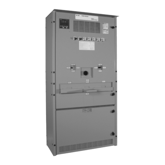
Instructions for Combination Bypass Isolation and Transfer Switches
100 - 1000 Amps
Effective July 2007 Supercedes I.L. 16913 dated February 1991
APPLICATION
The Cutler-Hammer combination Bypass Isolation and
Transfer Switches are listed under Underwriters'
Laboratories UL 1008 and CSA C22.2 No. 178 Standard
for Safety for Automatic Transfer Switches. The power
contact assemblies utilized in the ATSBI switches are
also covered under UL489 and CSA C22.2 No. 5 Standard
for Safety for Circuit breakers.
SAFETY PRACTICES
THE
CUTLER-HAMMER
ISOLATION AND TRANSFER SWITCH HAS BEEN
DESIGNED AND MANUFACTURED WITH BUILT-IN
INTERLOCKS AND SAFETY FEATURES INTENDED TO
PROVIDE SAFE AND PROPER OPERATING SEQUENCES.
TO PROTECT PERSONNEL ASSOCIATED WITH THE
INSTALLATION, OPERATION AND MAINTENANCE OF
THIS EQUIPMENT THE FOLLOWING PRACTICES MUST
BE FOLLOWED:
•
Only qualified persons, as defined in the national
Electrical Code, who are familiar with the installa-
tion and maintenance of low voltage circuits and
equipment should perform any work associated
with this equipment.
•
COMPLETELY READ AND UNDERSTAND THESE
INSTRUCTIONS before attempting any installation,
operation, maintenance, or modification of this
equipment.
•
ALWAYS TURN OFF AND LOCK OUT THE POWER
SOURCE(S) FEEDING THIS EQUIPMENT PRIOR TO
PERFORMING ANY INSTALLATION, MAINTENANCE,
OR MODIFICATION OF THIS EQUIPMENT. Failure
to do so could result in electrical shock leading to
death, personal injury, or property damage.
I.L. 16913A
FILE 29-900
WARNING
COMBINATION
BYPASS
Advertisement
Table of Contents

Summary of Contents for Eaton Cutler-Hammer BIHI
- Page 1 I.L. 16913A FILE 29-900 Instructions for Combination Bypass Isolation and Transfer Switches 100 - 1000 Amps APPLICATION The Cutler-Hammer combination Bypass Isolation and Transfer Switches are listed under Underwriters’ Laboratories UL 1008 and CSA C22.2 No. 178 Standard for Safety for Automatic Transfer Switches. The power contact assemblies utilized in the ATSBI switches are also covered under UL489 and CSA C22.2 No.
- Page 2 I.L. 16913A These instructions are not complete and may not A ratings nameplate will also be affixed to the contain all of the relevant information necessary switch identifying the withstand, interrupting, and to diagnose or solve a particular problem you closing ratings for which the unit is intended.
-
Page 3: Installation
I.L. 16913A mechanism operating handle, disconnect all power to the ATS power switching contacts. This allows the isolated ATS to be inspected or maintained with all power disconnected. 3. Bypass Switched The bypass switch permits power continuity to critical load circuits while the ATS is isolated. Normal and emergency bypass switches are provided to permit bypass to either power source, but both Bypass... - Page 4 I.L. 16913A Fig. 2 Note: For bottom entry, add 14” to depth of unit. Effective July 2007...
- Page 5 I.L. 16913A UL1008 Certified ATS BYPASS ISOLATION ATS ( 2&3 POLE ) Switch DIMENSIONS (INCHES/MM) Amps Volts Frame Bypass Frame 21/533 82.5/2095 2.4/61 5.3/135 7.5/191 25.5/648 24.5/6.23 30/965 79.5/2019 18/457 21/533 82.5/2095 2.4/61 5.3/135 7.5/191 25.5/648 24.5/6.23 30/965 79.5/2019 18/457 21/533 82.5/2095 2.4/61 5.3/135 7.5/191 25.5/648...
-
Page 6: Cable Connections
I.L. 16913A CABLE CONNECTIONS Test all power cables prior to connection to the unit to ensure that conductors or cable insulation has not been damaged while being pulled into position. Power cables are to be connected to solderless screw type lugs located at the top of the bypass switch. - Page 7 I.L. 16913A Energizing the equipment. The plug/sockets are WARNING keyed to only permit proper insertion alignment by pushing the plug into the socket until the latches click. IMPROPER POWER CABLE CONNECTIONS CAN CAUSE EXCESSIVE HEAT GENERATION AND ENGINE START CONNECTION SUBSEQUENT EQUIPMENT FAILURE.
- Page 8 I.L. 16913A Fig. 3 Effective July 2007...
- Page 9 I.L. 16913A Fig. 3 Effective July 2007 Supercedes I.L. 16913 dated February 1991...
-
Page 10: Functional Testing
I.L. 16913A Verify the phase to phase line voltages of both the NOT indicate a presence of voltage on the ATS power panel since the ATS logic panel senses on normal and emergency power sources are the same the line side of the Bypass switch. and that they match rated voltage as indicated on Utilizing a voltmetre measure phase-to-phase-to- the ATSBI equipment ratings label. - Page 11 I.L. 16913A Utilizing a voltmetre, measure phase-to-phase and See ATS Controller Manual for additional testing and phase-to-neutral voltages across the Emergency troubleshooting information. Bypass Line Terminal to insure Emergency voltage is correct. If necessary, make adjustments to the TRANSFER SWITCH REMOVAL voltage regulator on the generator according to the manufacturer’s recommendations to correct any Cutler-Hammer Automatic Transfer Switches typically...
- Page 12 I.L. 16913A TRIP RESET ISOLATION SWITCH RESET The Cutler-Hammer ATSBI Switch is supplied with An automatic opening of the Isolation Switch will be high interrupting molded case switches which visually indicated by a lit amber light on the Bypass function as the power contacts for the Transfer Isolation (upper) panel of the enclosure.
-
Page 13: Maintenance
I.L. 16913A The Cutler-Hammer ATSBI equipment can be optionally (16 and 17) equipped with integral CAUTION overcurrent (overload and short circuit) protection. If selected the standard Moulded Case Switches with A TRIPPED CONDITION IS A RESULT OF A instantaneous short circuit releases are replaced FAULTED POWER CIRCUIT CONNECTED TO THE with conventional circuit breakers equipped with EQUIPMENT. -
Page 14: Factory Maintenance
I.L. 16913A Good maintenance practices call for periodiic inspection of all electrical apparatus. Terminal lugs and bus connections should be periodically checked for lightness of the connections to avoid excessive heating and premature failure. The Moulded Case Switches employed in the equipment have self wiping contacts built in to the design of the switch.


Need help?
Do you have a question about the Cutler-Hammer BIHI and is the answer not in the manual?
Questions and answers