Table of Contents
Advertisement
Quick Links
Advertisement
Table of Contents

Related Manuals for Schaeffler SpindleSense


Summary of Contents for Schaeffler SpindleSense
- Page 1 Schaeffler SpindleSense User manual...
-
Page 3: Table Of Contents
Assistants ................15 Data acquisition ............... 19 Configuration................20 Log ................... 26 Transport and storage ....................27 Mounting Demands on the adjacent construction ........27 Cleanliness................27 Mechanical mounting ............... 28 Connection of the sensor ring............ 31 Schaeffler Technologies BA 61... - Page 4 Fault correction ................. 36 Dismounting Mechanical dismounting ............37 Cleaning..................37 Decommissioning ....................38 Disposal ....................38 Technical data and Interfaces .................. 39 accessories Voltage supply ................42 Connection cable............... 43 Approval and tests ..............44 BA 61 Schaeffler Technologies...
-
Page 5: About The User Manual Symbols
Schaeffler SpindleSense About the user manual This user manual describes the Schaeffler SpindleSense system. The associated setup software “Service Setup Tool” (SST) is described in the following version: 3.45.02972M. Symbols The warning and hazard symbols are defined in accordance with ANSI Z535.6–2011. -
Page 6: General Safety Guidelines Usage For The Intended Purpose
Any use involving a safety-related application of the measurement values is excluded. The safety of the machine tool, ambient systems the intended purpose and of persons must be taken into account. Application areas in which the use of Schaeffler SpindleSense is not permitted: explosive environments (ATEX) nuclear power... -
Page 7: Electromagnetic Compatibility
Extensive tests have been carried out to verify electromagnetic compatibility (EMC), see table, page 44. Qualified personnel Schaeffler SpindleSense may only be mounted, commissioned, operated and maintained by qualified personnel. The scope of competence, area of responsibility and monitoring of personnel must be precisely regulated by the site operator. -
Page 8: Safety Regulations
Schaeffler SpindleSense Safety regulations This section contains important safety regulations relating to work- ing with Schaeffler SpindleSense. Further guidelines can be found in the individual chapters of this user manual. General handling Schaeffler SpindleSense is a sensitive measuring system. Shocks and compressive loads can damage the components, render the system unusable or result in erroneous output values. -
Page 9: Scope Of Delivery Damage During Transit
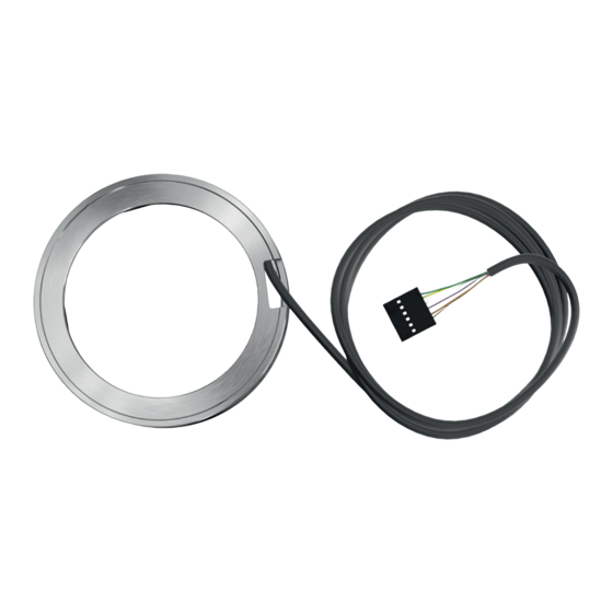
Scope of delivery The scope of delivery of Schaeffler SpindleSense includes: sensor unit, comprising sensor ring with connection cable and provisional plug, radial measurement ring and axial measurement ring safety guidelines. Schaeffler SpindleSense Sensor unit +120 °C +120 °C +248 °F +248 °F... -
Page 10: Description Design
Schaeffler SpindleSense Description Schaeffler SpindleSense is a compact measuring system for use in machine tools. It measures displacements of the shaft relative to the housing. When used in combination with FAG spindle bearings, the option of overload detection is also available. In this case, Schaeffler... -
Page 11: Measurement Principle
These influences must be taken into consideration in the interpretation of the measurement results. To ensure the displacement measurement is interpreted correctly, it is essential that Schaeffler carry out a comprehensive analysis of the application. Functional scope Schaeffler SpindleSense is supplied as standard in a basic version with displacement measurement (functional scope: C-A1). -
Page 12: Coordinate System
Schaeffler SpindleSense Coordinate system A coordinate system is defined for the sensor ring in Schaeffler SpindleSense. Sensor ring Radial measurement ring Axial measurement ring Marking: z axis Figure 5 Coordinate system of the sensor ring Characteristics of the coordinate system:... -
Page 13: Setup Software Logging In And User Levels
Schaeffler provides the software for download, see section Installation of the setup software SST, page 32. Following setup, Schaeffler SpindleSense will then run in normal operation without setup software SST. Logging in and user levels The buttons for logging in and for selecting a user level are located at the top right of the program window, Figure 6. - Page 14 [Service] Internal Schaeffler user level, contains the permissions required for service activities. [Production] Internal Schaeffler user level, contains the permissions required for production and factory configuration.
-
Page 15: General Settings And Alarm Status
[License]: information about the licence [About]: information about the program version and current system. Symbol Definition Alarm status: green = no alarm red = alarm. Schaeffler Technologies BA 61... -
Page 16: Connection To The Sensor Ring
Schaeffler SpindleSense Connection to the sensor ring The buttons for the connection to the sensor ring are located at the top right of the program window, Figure 8. Figure 8 Buttons for connection to the sensor ring Restart and connection status... -
Page 17: Assistants
A status is displayed for these assistants. Status Symbol Definition All requisite data are available in the sensor ring. Not all requisite data are available in the sensor ring. Figure 9 Assistants in the setup software SST Schaeffler Technologies BA 61... - Page 18 Schaeffler. [Spindle parameters] Assistant for reading in spindle-specific parameters with the aid of a BLOB file. The BLOB file will be made available to you by Schaeffler. [Machine parameters] Assistant for reading in machine-specific parameters with the aid of an INI file.
- Page 19 Step – Depending on the user level, a password can be assigned for the parameter set. Click on [Next] to save the new parameter set in the sensor ring and complete the process. Schaeffler Technologies BA 61...
- Page 20 Schaeffler SpindleSense Figure 10 Assistant [Machine parameters] (screenshots) BA 61 Schaeffler Technologies...
-
Page 21: Data Acquisition
–1 –1 The zero position can only be set at speeds of 60 min 20 min Speed simulator The spindle speed can be simulated for commissioning and test purposes. Figure 11 [Data acquisition] Schaeffler Technologies BA 61... -
Page 22: Configuration
Schaeffler SpindleSense Configuration The following functions are available under the [Configuration] tab, Figure 12: display and modification of the parameters stored in the sensor ring display of product information on the sensor ring password management firmware update. Importing and exporting... - Page 23 The buttons with a grey background are used to read the parameters stored on the sensor ring, while the buttons with a green background are used to save the displayed parameters on the sensor ring. Figure 13 [Parameters] (screenshot) Schaeffler Technologies BA 61...
- Page 24 [Max. value for threshold Upper limit applicable to threshold for ball excursion] ball excursion These upper limits are set by Schaeffler. They cannot be changed by the spindle or machine manufacturer. [General machine settings] Parameter field Definition [CAN-Node Number of the sensor ring in the CAN bus.
- Page 25 Period between the occurrence of an alarm event and continuation of the measurement. This value is required for writing an alarm event in the LOG file. [Output frequency] Frequency of data output on the CAN bus Schaeffler Technologies BA 61...
- Page 26 Schaeffler SpindleSense Display of product information on Information on the sensor ring and its fitted components can be the sensor ring information], Figure 14. accessed under [Product Figure 14 [Product information] (screenshot) BA 61 Schaeffler Technologies...
- Page 27 The password is transferred to the sensor ring by selecting [Send password configuration]. Figure 15 [Password] (screenshot) Firmware update The firmware for the sensor ring can be updated under [Update firmware], Figure 16. Figure 16 [Update firmware] (screenshot) Schaeffler Technologies BA 61...
-
Page 28: Log
Schaeffler SpindleSense The events logged by the system can be viewed under the [Log] tab, Figure 17, for example overload, faults or changes made by the operator to parameters and thresholds. Figure 17 [Log] BA 61 Schaeffler Technologies... -
Page 29: Transport And Storage
We recommend checking the adjacent construction with respect to the criteria stipulated therein before starting mounting work. Further information TPI 258, Schaeffler SpindleSense. Cleanliness Contamination can impair the function of the sensors. To protect against contamination: ... -
Page 30: Mechanical Mounting
Schaeffler SpindleSense Mechanical mounting The mounting process can vary depending on the design integration of Schaeffler SpindleSense into the adjacent construction. In principle, the following apply: The sensor ring and the two measurement rings can be mounted individually. The arrangement of the sensor ring and measurement rings is determined by the adjacent construction. - Page 31 Observe the maximum heating temperature of +120 °C. Press the heated measurement ring promptly onto the shaft. Further information Further information on thermal mounting: MH 1, Mounting Handbook TPI 200, Induction Heating Devices HEATER. Schaeffler Technologies BA 61...
- Page 32 Schaeffler SpindleSense Sensor ring The sensor ring is fitted in the housing with a clearance fit and secured by means of axial clamping: Excessive temperatures can damage the sensor ring. Refrain from heating the sensor ring in any way.
-
Page 33: Connection Of The Sensor Ring
Sensor ring Connection cable Plug Extension cable Customer control system Shielding Cable shielding separated from the housing Figure 19 Shielding concept Schaeffler Technologies BA 61... -
Page 34: Commissioning Connecting The Sensor Ring To A Windows Pc
Installation of Installation: the setup software SST Download the “Service Setup Tool” (SST) software for Schaeffler SpindleSense to a Windows PC using the following link: https://www.schaeffler.de/std/1F3B Run the setup routine and follow the instructions. Selection of the sensor ring... - Page 35 If only one sensor ring is connected to the Windows PC, the start page of the setup software SST is displayed with the [Overview] tab open and the assistant selection is also displayed, Figure 9, page 15. Schaeffler Technologies BA 61...
-
Page 36: Selection Of The User Level
Schaeffler SpindleSense Selection of the user level Before configuring the sensor ring, a suitable user level must be selected: Log into the setup software SST, selecting the appropriate user level for the pending configuration, see page 11. With the exception of the... -
Page 37: Operation
Operation Once successfully commissioned and configured, Schaeffler SpindleSense will run autonomously. The system continuously measures displacements of the main spindle and, depending on the configuration, sends messages and data to downstream systems. Permissible indirect process The resistance of the potting material used in the sensor ring... -
Page 38: Troubleshooting And Essential Guidelines
Check that all components are fitted correctly and the sensor ring is connected correctly. Check the configuration of the sensor ring. Disconnect the voltage supply to the sensor ring and then reconnect. If the fault persists, please contact Schaeffler. BA 61 Schaeffler Technologies... -
Page 39: Dismounting Mechanical Dismounting
The tools commonly used in rolling bearing technology, such as mechanical or hydraulic extractors, can be used to dismantle Schaeffler SpindleSense. The sensor ring and the measurement rings are removed separately. Dismounting forces directed through the potting of the sensor ring’s electronics can damage the electronics. -
Page 40: Decommissioning
Schaeffler SpindleSense Decommissioning If Schaeffler SpindleSense can no longer be operated safely, the system must be taken out of operation and secured against inadvertent operation. Safe operation is then no longer possible if a component: shows visible signs of damage... -
Page 41: Technical Data And Interfaces
Technical data and accessories Interfaces Schaeffler SpindleSense contains the following interfaces, Figure 22, Figure 23 and table, page 40: CAN bus as communications interface between the sensor ring and Windows PC and for the output of measurement data for further processing. Configuration software provides comprehen-... - Page 42 Schaeffler SpindleSense Interface characteristics Name Characteristic CAN bus Symbol rate 1 MBd (High-Speed-CAN) Proprietary Voltage supply DC 24 V D-Out Digital output Output voltage normal operation 24 V (constant) (signal type) alarm (overload) 0 V (constant) error 0 V to 24 V...
- Page 43 If a single participant is connected directly to the Windows PC via the CAN-USB adapter, a terminating resistance of 120 must also be provided in this instance. CAN-USB Pin 5 adapter Pin 6 Windows Figure 26 CAN bus termination, 1 sensor ring Schaeffler Technologies BA 61...
-
Page 44: Voltage Supply
Schaeffler SpindleSense CAN objects Special CAN objects are available for exchanging data between a sensor ring and other CAN bus participants, for example a Windows CAN objects Name Direction Description Configuration Transmission of requirements to the sensor ring Response Receipt of replies, error messages or... -
Page 45: Connection Cable
Connection cable Schaeffler SpindleSense is supplied with a 6-pin, 2-m-long connec- tion cable, which is not suitable for drag chain use. The cable can be shortened to the required length once fitted in the spindle. The cable is fitted with a temporary plug, which is used for simple initial configuration and to protect the cords during transport. -
Page 46: Approval And Tests
Schaeffler SpindleSense Approval and tests Extensive tests have been carried out to verify electromagnetic compatibility (EMC). Tests for Standard Value electromagnetic compatibility EN 61326-1:2013 – EN 61000-4-2:2009 4 kV Contact-D, 8 kV Air-D EN 61000-4-3:2011-04 10 V/m at 80 MHz to 1 GHz;... - Page 48 Germany We reserve the right to make technical Internet www.schaeffler.de/en changes. E-mail info.de@schaeffler.com In Germany: © Schaeffler Technologies AG & Co. KG Phone 0180 5003872 Issued: 2020, November 0180 5003873 This publication or parts thereof may not From other countries: be reproduced without our permission.
Need help?
Do you have a question about the SpindleSense and is the answer not in the manual?
Questions and answers