Advertisement
Quick Links
Advertisement

Related Manuals for Schaeffler RUE-F Series


Summary of Contents for Schaeffler RUE-F Series
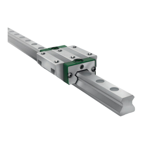
- Page 1 Linear Recirculating Roller Bearing and Guideway Assembly RUE-F Mounting manual...
- Page 3 Guidance systems should only be fitted using the tools specified. Machines, devices or equipment that generate cutting debris or dust must not be used in the vicinity of the fitting area. The adjacent construction should be kept clean. Schaeffler Technologies MON 103...
- Page 4 Locating heights and corner radii Locating heights and corner radii Designation Locating heights Corner radii max. max. max. RUE35-F (-L, -H, -HL) RUE45-F (-L, -H, -HL) RUE55-F (-L, -H, -HL) RUE65-F (-L, -H, -HL, SL) 10,5 MON 103 Schaeffler Technologies...
- Page 5 Values for geometry and position Guideway Preload class V1, V2 , V4, V5 Parallelism, flatness, perpendicularity TSX35-E TSX45-E TSX55-E TSX65-E Valid for all guideway variants. Standard preload class. Schaeffler Technologies MON 103...
- Page 6 RUE-F Not convex (for all machined surfaces) Figure 2 Tolerances of mounting surfaces and parallelism of mounted units Not convex (for all machined surfaces) Figure 3 Tolerances of mounting surfaces and parallelism of mounted units MON 103 Schaeffler Technologies...
- Page 7 Maximum permissible deviation from the theoretically precise position, Figure 2, page 4 – Factor, dependent on the preload class, see table Centre distances between guidance elements Factor a Preload class Factor 0,15 0,09 0,075 0,06 0,06 Standard preload class. Schaeffler Technologies MON 103...
-
Page 8: Checking The Scope Of Delivery
Bend the ends up slightly at both ends of the carriage. The spring steel strip must be produced by the customer. Figure 5 Spring steel strip with bent ends at both ends of the carriage MON 103 Schaeffler Technologies... - Page 9 Alternatively, carriages can also be lubricated from , Figure 7. above via the adjacent construction Lubrication from the side Lubrication from above Figure 7 Lubrication Other lubrication connectors for grease or oil lubrication are avail- able as accessories. Schaeffler Technologies MON 103...
- Page 10 DIN 7984-8.8 RUE35-F (-L) RUE35-F-H (-HL) – – – – RUE45-F (-L) RUE45-F-H (-HL) – – – – RUE55-F (-L) RUE55-F-H (-HL) – – – – RUE65-F (-L) RUE65-F-H (-HL, -SL) – – – – ▲ continued MON 103 Schaeffler Technologies...
- Page 11 Slide the carriage from the dummy guideway onto the guideway. Keep the dummy guideway for further mounting operations. Schaeffler Technologies MON 103...
- Page 12 Linear recirculating roller bearing and guideway assemblies RUE-F Dummy guideway Guideway Figure 9 Dismantling and fitting the carriage Right-angled end Chamfered end Figure 10 Ends of the dummy guideway MON 103 Schaeffler Technologies...
- Page 13 If multi-piece guideways are used, observe the correct sequence of the guideways The gap at the end face must be 0,05 mm. Figure 12 Observing the correct sequence of the guideways and checking the gap dimension Schaeffler Technologies MON 103...
- Page 14 . In each step, tighten the screws marked in red first, followed by the screws marked in black. For tightening torque M see table, page 8. Figure 14 Tightening the screws in accordance with the tightening scheme MON 103 Schaeffler Technologies...
- Page 15 Drive the closing plugs in flush using a hammer and press-in block Figure 15 Driving in the plastic closing plugs Do not work the plastic closing plugs using an oil stone similar implement. Figure 16 Do not work the plastic plugs using an oil stone Schaeffler Technologies MON 103...
- Page 16 Do not use an oil stone or similar implement on the surfaces of guideways treated with coatings. Figure 18 Smoothing the surfaces using an oil stone Clean the surfaces using a lint-free cloth. MON 103 Schaeffler Technologies...
- Page 17 Press the closing plug in flush using the fitting device MVH.TSX Fitting device MVH.TSX optionally available as an accessory. Connect fitting device MVH.TSX to the hydraulic source ensure that the bleed is activated. Figure 20 Preparing and positioning the fitting device Schaeffler Technologies MON 103...
- Page 18 Do not use an oil stone or similar implement on the surfaces of guideways treated with coatings. Figure 22 Smoothing the surfaces using an oil stone Clean the surfaces using a lint-free cloth. MON 103 Schaeffler Technologies...
- Page 19 Align the carriages with the holes in the machine table place the table without shock contact on the carriages Figure 24 Aligning the carriages and positioning the machine table without shock contact Schaeffler Technologies MON 103...
- Page 20 In each step, tighten the screws marked in red first, followed by the screws marked in black. For tightening , see table, page 8. torque M Figure 26 Tightening the screws in accordance with the tightening scheme MON 103 Schaeffler Technologies...
- Page 21 Check that the recirculating unit runs uniformly by moving the table. If necessary, fully locate the guideway in relation to the bed and table , for example by means of synthetic resin. Figure 28 Checking that the recirculating unit runs uniformly Schaeffler Technologies MON 103...
- Page 22 Standard lubrication connector similar to DIN 71412-A-M6 Figure 30 Lubrication connector on the end face or sides Close off the upper hole using the grub screw supplied (included in the lubrication set MSatzRWU). MON 103 Schaeffler Technologies...
- Page 23 O ring: RUE35-F to RUE55-F: NBR70 similar to ISO 3601-10 1,5 RUE65-F: NBR70 similar to ISO 3601-18 1,5 Figure 31 Inserting the O ring Figure 32 Screwing the grub screw into place and positioning the adjacent construction Schaeffler Technologies MON 103...
- Page 24 RUE65-F (-H) RUE65-F-L (-HL, -SL) Initial grease quantities Designation Initial grease quantity for RUE..-F RUE35-F (-H) RUE35-F-L (-HL) RUE45-F (-H) 11,5 RUE45-F-L (-HL) 16,1 RUE55-F (-H) 20,7 RUE55-F-L (-HL) 25,3 RUE65-F (-H) RUE65-F-L (-HL, -SL) 28,8 MON 103 Schaeffler Technologies...
- Page 25 /P = 8 ■ v = 0,8 m/s ■ stroke 500 mm to 1000 mm ■ independent of mounting positions, 0° to 90° ■ temperature +20 °C to +40 °C ■ lubrication connector on one side Schaeffler Technologies MON 103...
- Page 26 SMDS impulses quantity RUE35-F-SMDS (-H) 0,075 RUE35-F-L-SMDS (-HL) 0,075 RUE45-F-SMDS (-H) 0,165 RUE45-F-L-SMDS (-HL) 0,175 RUE55-F-SMDS (-H) 0,165 RUE55-F-L-SMDS (-HL) 0,175 RUE65-F-SMDS (-H) 0,725 RUE65-F-L-SMDS (-HL, -SL) 1 0,74 MON 103 Schaeffler Technologies...
- Page 28 This publication supersedes all deviating infor- mation from older publications. Printing, including Phone 0180 5003872 excerpts, is only permitted with our approval. From other countries: © Schaeffler Technologies AG & Co. KG Phone +49 9721 91-0 MON 103 / en-GB / DE / 2021-11...
Need help?
Do you have a question about the RUE-F Series and is the answer not in the manual?
Questions and answers