Table of Contents
Advertisement
Available languages
Available languages
Quick Links
Advertisement
Chapters
Table of Contents

Related Manuals for Benning PV 2


Summary of Contents for Benning PV 2
- Page 1 Bedienungsanleitung Operating manual...
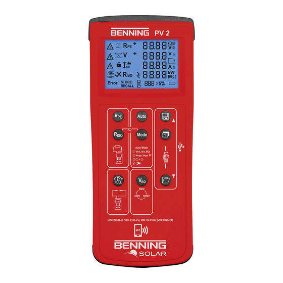
- Page 2 Bild 1: Gerätefrontseite Fig. 1: Appliance front face Fig. 1: Front tester panel Bild 2: Geräteoberseite Fig. 2: Top side of the device Fig. 2: Top side of the device 12/ 2017...
- Page 3 Bild 3: Digitalanzeige Fig. 3: Digital display Bild 4: Nullabgleich der Sicherheitsmessleitung für -Messung Fig. 4: Null balance of the measuring lead for R measurement 12/ 2017...
- Page 4 PV-Modul/ -Strang Bild 5: Prüfung des Schutzleiterwiderstandes R PV-module/ -string Fig. 5: Testing the protective conductor resistance (R PV-Modul/ -Strang Bild 6: Automatische Solarmodul-Messung, ISO- PV-module/ -string Messung über Erdleiter Fig. 6: Automatic solar panel measurement, ISO Max. measurement via earthing conductor Nicht an parallel geschalteten...
- Page 5 Spannungsmessung über 4 mm Prüfbuchsen Fig. 7: Voltage measurement via 4 mm test sockets Bild 8: AC/ DC-Strommessung mit optionalem Stromzangenadapter BENNING CC 3 Fig. 8: AC/ DC current measurement by means of optional current clamp adapter BENNING CC 3...
- Page 6 Bild 9: Isolationswiderstandsmessung R (2-polig) Fig. 9: Insulating resistance measurement R (2-pin) PV-Modul/ -Strang PV-modul/ -string Bild 10: Anzeige der I-U Kennlinie über Android-Gerät Fig. 10: Displaying the I-V characteristic via an Android device 12/ 2017...
- Page 7 Bild 11: Funkverbindung zum optionalen Einstrahlungs- und Temperaturmessgerät BENNING SUN 2 Fig. 11: Radio connection to the optional insolation and temperature measuring instrument BENNING SUN 2 PV-Modul/ -Strang PV-module/ -string Max. Bild 12: Batterie-/ Sicherungswechsel Fig. 12: Battery/ fuse replacement...
-
Page 8: Table Of Contents
Prüfung des Batteriezustandes 8.1.5 Kompensation der Sicherheitsmessleitungen (Nullabgleich) 8.2 Prüfung des Schutzleiterwiderstandes, RPE 8.3 Automatische Messungen am PV-Generator 8.4 Gleich- und Wechselspannungsmessung 8.5 Strommessung mit optionalem AC/ DC-Stromzangenadapter BENNING CC 3 8.6 Isolationswiderstandsmessung (RISO, 2-polig) 8.7 Messwertspeicher 8.7.1 Messwerte speichern 8.7.2 Messwerte aufrufen 8.7.3... -
Page 9: Sicherheitshinweise
PV-Wechselrichter kann zur Beschädigung des BENNING PV 2 führen! Die PV-Prüfbuchsen sind ausschließlich für die Kontaktierung mit PV-Generatoren (PV-Modul, PV-Strang) vorgesehen. Das Prüfgerät BENNING PV 2 direkt nach beendeter Prüfung vom PV-Generator trennen. Messspitzen nicht berühren! Bei Isolationswiderstandsmessungen können hohe elektrische Spannungen an den Messspitzen anliegen. -
Page 10: Lieferumfang
Über die 4 mm Sicherheitsmessleitungen sind Spannungsmessungen an Steckdosenstromkreise möglich. Das BENNING PV 2 darf über die 4 mm Prüf- buchsen nur in Stromkreisen der Überspannungskategorie III mit max. 300 V AC/DC Leiter gegen Erde benutzt werden. Bei Spannungsmessun- gen über die 4 mm Prüf buchsen sind vorher die PV-Sicherheitsmess- leitungen von den PV-Prüfbuchsen... -
Page 11: Gerätebeschreibung
Gerätebeschreibung Digitalanzeige -Taste -Taste -Taste -Taste -Taste -Taste NFC-Sensor -Taste USB-Schnittstelle -Taste -Taste + PV-Prüfbuchse (rot) – PV-Prüfbuchse (schwarz) – 4 mm Prüfbuchse (schwarz) + 4 mm Prüfbuchse (rot) Displayanzeige: Spannungs-Polaritätsanzeige Stromzangen-Messung (Null-Offset), standes. (Achtung, heiße Oberfläche) (Polaritätsanzeige) (Achtung, gefährliche Spannung) -
Page 12: Allgemeine Angaben
viert wurde. (Achtung) Auswahl der Isolationsprüfspannung, messung an. Error (Fehler), STORE, RECALL, Speicherplatzanzeige, Clr Einstrahlungsänderung, Batteriesymbol, erscheint bei entladenen Batterien Kennliniensymbol Allgemeine Angaben aus. Umgebungsbedingungen und schwarze und schwarze Elektrische Angaben 7.1 Schutzleiterwiderstand R Messbereich Auflösung Messgenauigkeit 12/ 2017... -
Page 13: Prüfen Mit Dem Benning Pv 2
7.6 Spannung über 4 mm Prüfbuchsen Messgenauigkeit Messbereich Auflösung (DC, AC 50 Hz - 60 Hz) 7.7 Strom mit AC/ DC Stromzangenadapter BENNING CC 3 Messgenauigkeit Messbereich Auflösung (DC, AC 50 Hz - 60 Hz) Prüfen mit dem BENNING PV 2 8.1 Vorbereiten der Prüfung... -
Page 14: Prüfung Des Schutzleiterwiderstandes, Rpe
Spannung angezeigt. Steigt die Messspannung an den Prüfspitzen über 30 V wird die R -Messung blockiert! Wird die R -Messung unterhalb von 30 V gestartet, kann eine niederohmige Spannungsquelle die eingebaute Sicherung im BENNING PV 2 auslösen! buchse speichern. 12/ 2017... -
Page 15: Automatische Messungen Am Pv-Generator
Gemäß DIN EN 62446 sind die Messungen pro PV-Strang durchzuführen! Eine Messung an parallel geschalteten PV-Strängen oder eine Kontaktierung am PV-Wechselrichter kann zur Überlastung des BENNING PV 2 führen! Der PV-Generator muss von der elektrischen Hauptversorgung isoliert sein! Weder Plus- noch Minuspol des PV-Generators darf geerdet sein! Alle Messleitungen sind sicher mit dem PV-Generator zu kontaktieren. - Page 16 Mode - Is/c Kurzschlussstrom Isolationswiderstand Mode : „ - Is/c Kurzschlussstrom Mode „ - Is/c Kurzschlussstrom Isolationswiderstand Mode I-U Kennlinienmessung wird durchgeführt. Bewegung I-U Kennlinienmessung ist beendet. schlussstrom Is/c wird eingeblendet 12/ 2017...
-
Page 17: Gleich- Und Wechselspannungsmessung
Grenzwert Isolationswiderstand 1000 V 8.4 Gleich- und Wechselspannungsmessung +/ – +/ – speichern. 8.5 Strommessung mit optionalem AC/ DC-Stromzangenadapter BENNING CC 3 angezeigt. speichern. 8.6 Isolationswiderstandsmessung R (2-polig) Der PV-Generator muss von der elektrischen Hauptversorgung isoliert sein! Weder Plus- noch Minuspol des PV-Generators darf geerdet sein! Bei Anliegen einer Spannung von >... -
Page 18: Messwertspeicher
erscheint. angezeigt. speichern. 8.7 Messwertspeicher ob die Messwerte gespeichert werden sollen. speichern. cherplatznummer . Die Speicherplatznummer dargestellt. wird zum vorherigen Speicherplatz gewechselt. speichers abgebrochen. 12/ 2017... -
Page 19: Funkverbindung Zu Einstrahlungs- Und Temperaturmessgerät Benning Sun
Hinweis: lichen werden. eingeblendet. eingeblendet. Hinweise zum Datentransfer: 8.8 Funkverbindung zu Einstrahlungs- und Temperaturmessgerät BENNING SUN 2 - Wireless SUN link derlich. und die und die 12/ 2017... -
Page 20: Instandhaltung
Messbereiches liegt. Hinweis: Instandhaltung Vor dem Öffnen das BENNING PV 2 unbedingt spannungsfrei machen! Elektrische Gefahr! ausschließlich Elektrofachkräften vorbehalten, die dabei besondere Maßnahmen zur Unfallverhütung treffen müssen. 9.1 Fehlercodes Fehlercode Abhilfe schritten. Die Messung wurde abgebrochen. 12/ 2017... -
Page 21: Sicherstellen Des Gerätes
oder etc. und betätigen Sie gleichzeitig 9.2 Sicherstellen des Gerätes und gegen erneute Nutzung zu sichern. 9.3 Reinigung 9.4 Batteriewechsel Vor dem Öffnen des Gerätes sind alle Messleitungen zu entfernen! Elektrische Gefahr! erscheint. Schalten Sie das 12/ 2017... -
Page 22: Sicherungswechsel
Leisten Sie Ihren Beitrag zum Umweltschutz! Batterien dürfen nicht in den Hausmüll. Sie können bei einer Sammelstelle für Altbatterien bzw. Sondermüll abgegeben werden. Informieren Sie sich bitte bei ihrer Kommune. 9.5 Sicherungswechsel Vor dem Öffnen des Gerätes sind alle Messleitungen zu entfernen! Elektrische Gefahr! dem Sicherungshalter. - Page 23 8.2 Testing the protective conductor resistance (RPE) 8.3 Automatic measurements on the PV generator 8.4 AC/ DC voltage measurement 8.5 Current measurement by means of optional AC/ DC current clamp adapter BENNING CC 3 8.6 Insulating resistance measurement RISO (2-pin) 8.7 Measured value memory 8.7.1...
-
Page 24: Safety Note
PV generators (PV module, PV string). Disconnect the BENNING PV 2 from the PV generator directly after the test. Do not touch the measuring probes! During insulating resistance measurements, high electric currents might be applied to the measuring probes. -
Page 25: Scope Of Delivery
Use the BENNING PV 2 only in compliance with the intended use specified in this documentation. If the BENNING PV 2 is used in a manner not specified by this document then the protection provided by the equipment may be impaired. -
Page 26: Unit Description
Unit description Digital display -key -key -key -key -key -key NFC sensor -key USB interface -key -key + PV test socket (red) - PV test socket (black) - 4 mm test socket (black) clip + 4 mm test socket (red) -
Page 27: General Information
Error STORE RECALL Storage location indication Change of insolation Battery symbol Curve symbol General information PV 2 to cool down. Environment conditions: the red the red Electrical specifications 7.1 Protective conductor resistance R Measuring range Resolution Measuring accuracy 7.2 PV module/ PV string, open-circuit voltage, (Vo/c) - Page 28 (DC, AC 50 Hz - 60 Hz) Measuring with the BENNING PV 2 8.1 Preparation for measuring readings and measuring errors. Before starting the BENNING PV 2, always check the device, the leads and the test object for damages. APO Auto Power- APO Auto-Power-O Press and hold the .
-
Page 29: Testing The Protective Conductor Resistance (Rpe)
If the measuring voltage at the probe tips exceeds 30 V, the R measurement will be blocked! If the R measurement is started below 30 V, a low-impedance voltage source might trip the built-in fuse of the BENNING PV 2! and connect the test object. Press the Press the to store the measured value to the next storage location available. -
Page 30: Automatic Measurements On The Pv Generator
Measuring at PV strings connected in parallel or contacting at the PV inverter might involve damages of the BENNING PV 2! The PV generator must be isolated from the electric power supply! Neither the positive nor the negative pole of the PV generator must be earthed! Make sure that all measuring lines are safely connected to the PV generator. - Page 31 Mode Mode Mode Press the I-V curve measurement is running. I-V curve measurement is completed. Press the is pressed. Press the to store the measured value to the next storage location available. 12/ 2017...
-
Page 32: Ac/ Dc Voltage Measurement
R measurement will be blocked! Do not connect the measuring probes to a voltage source during R measurement, as the built-in fuse of the BENNING PV 2 might trip! and connect the test object. Press the Press the Press the to store the measured value to the next storage location available. -
Page 33: Measured Value Memory
8.7 Measured value memory date/ time stamp. the measured values shall be stored. Press the to store the measured value to the next storage location available. Press the to recall the stored measured values with the corresponding storage location number Press the again to go to the previous storage location. -
Page 34: Radio Connection To Insolation / Temperature Measuring Instrument Benning Sun
Notes on data transfer: is shown 8.8 Radio connection to insolation / temperature measuring instrument BENNING SUN 2 – wireless SUN link and the Press and hold the and the seconds. above the measured insolation value is outside the measuring range. -
Page 35: Maintenance
Maintenance Before opening the BENNING PV 2, make quite sure that it is voltage free! Electrical danger! may be carried out only by skilled electricians with special precautions for the prevention of accidents. 9.1 Error codes Error codes Remedy reached the maximum admissible temperature. Discon- and let it cool down. -
Page 36: Securing The Instrument
Incorrect measurement results. 9.3 Cleaning 9.4 Battery replacement Before opening the BENNING PV 2 ensure that all the test leads have been disconnected from the BENNING PV 2. Danger of electric shock! unit Make your contribution to environmental protection! Do not dispose of discharged batteries in the household garbage. -
Page 37: Calibration
Note: service. 9.6 Calibration 9.7 Spare parts 10. Environmental notice 12/ 2017... - Page 38 Benning Elektrotechnik & Elektronik GmbH & Co. KG Münsterstraße 135 - 137 D - 46397 Bocholt Phone: +49 (0) 2871 - 93 - - 93 - 429...
Need help?
Do you have a question about the PV 2 and is the answer not in the manual?
Questions and answers