Table of Contents
Advertisement
Quick Links
Chipsmall Limited consists of a professional team with an average of over 10 year of expertise in the distribution
of electronic components. Based in Hongkong, we have already established firm and mutual-benefit business
relationships with customers from,Europe,America and south Asia,supplying obsolete and hard-to-find components
to meet their specific needs.
With the principle of "Quality Parts,Customers Priority,Honest Operation,and Considerate Service",our business
mainly focus on the distribution of electronic components. Line cards we deal with include
Microchip,ALPS,ROHM,Xilinx,Pulse,ON,Everlight and Freescale. Main products comprise
IC,Modules,Potentiometer,IC Socket,Relay,Connector.Our parts cover such applications as commercial,industrial,
and automotives areas.
We are looking forward to setting up business relationship with you and hope to provide you with the best service
and solution. Let us make a better world for our industry!
Contact us
Tel: +86-755-8981 8866 Fax: +86-755-8427 6832
Email & Skype: info@chipsmall.com Web: www.chipsmall.com
Address: A1208, Overseas Decoration Building, #122 Zhenhua RD., Futian, Shenzhen, China
Advertisement
Table of Contents

Related Manuals for Analog Devices AD6642


Summary of Contents for Analog Devices AD6642
- Page 1 Chipsmall Limited consists of a professional team with an average of over 10 year of expertise in the distribution of electronic components. Based in Hongkong, we have already established firm and mutual-benefit business relationships with customers from,Europe,America and south Asia,supplying obsolete and hard-to-find components to meet their specific needs.
-
Page 2: Features
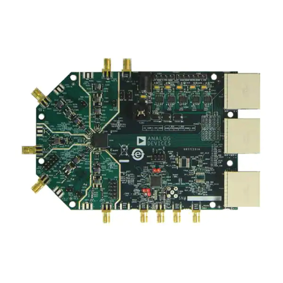
VisualAnalog SPI controller TYPICAL MEASUREMENT SETUP Figure 1. AD6642 and AD6657 Evaluation Board and HSC-ADC-EVALCZ Data Capture Board Rev. 0 | Page 1 of 32 Please see the last page for an important warning and disclaimers. -
Page 3: Table Of Contents
UG-232 Evaluation Board User Guide TABLE OF CONTENTS Features ....................1 Input Signals...................3 Equipment Needed ................1 Output Signals ................3 Software Needed ................1 Default Operation and Jumper Selection Settings ....5 Documents Needed ................1 Evaluation Board Software Quick Start Procedures .....6 ... -
Page 4: Evaluation Board Hardware
1.8 V for digital support circuitry the AD6642 or AD6657. It is critical that the signal sources used on the board, DVDD. This should also have a 1 A current for the analog input and clock have very low phase noise (<1 ps... - Page 5 UG-232 Evaluation Board User Guide WALL OUTLET 100V TO 240V AC 47Hz TO 63Hz SWITCHING POWER SUPPLY SWITCHING POWER 6V DC SUPPLY 2A MAX 6V DC 2A MAX SIGNAL SYNTHESIZER ANALOG FILTER SIGNAL SYNTHESIZER RUNNING ADC ANALYZER OR VISUAL ANALOG USER SOFTWARE SIGNAL SIGNAL...
-
Page 6: Default Operation And Jumper Selection Settings
50 Ω impedance. This input network is optimized to support a wide frequency band. See A differential LVPECL clock driver output can also be used to the AD6642 and AD6657 data sheets for additional information on clock the ADC input using the AD9517 (U901). -
Page 7: Evaluation Board Software Quick Start Procedures
Connect a low jitter sample clock to the connector J702. When using the AD6642 version of the ADC evaluation board, use a clean signal generator with low phase noise to provide an input signal to the desired A and/or B channel(s). - Page 8 Evaluation Board User Guide UG-232 COLLAPSE DISPLAY Figure 7. VisualAnalog – [Canvas – (AD6657 FFT)*], Main Window Setting Up the SPI Controller Software After the ADC data capture board setup is complete, set up the SPIController software using the following procedure: Open the SPI controller software by going to the Start menu or by double-clicking the SPIController software desktop icon.
- Page 9 UG-232 Evaluation Board User Guide Click the New DUT button in the SPIController window Note that other settings can be changed on the ADCBase 0 (see Figure 9). page (see Figure 10) and the ADC A and ADC B pages (see Figure 11) to set up the part in the desired mode (ADC C NEW DUT BUTTON and ADC D can also be changed if using the AD6657).
- Page 10 Evaluation Board User Guide UG-232 Adjusting the Amplitude of the Input Signal The next step is to adjust the amplitude of the input signal for each channel as follows: Adjust the amplitude of the input signal so that the fundamental is at the desired level.
- Page 11 UG-232 Evaluation Board User Guide Troubleshooting Tips The result should show an FFT plot that looks similar to Figure 18. If the FFT plot appears abnormal, do the following: • If you see a normal noise floor when you disconnect the signal generator from the analog input, be sure you are not overdriving the ADC.
-
Page 12: Evaluation Board Schematics And Artwork
Evaluation Board User Guide UG-232 EVALUATION BOARD SCHEMATICS AND ARTWORK Figure 20. DUT and Related Circuits Rev. 0 | Page 11 of 32... - Page 13 UG-232 Evaluation Board User Guide Figure 21. Board Power Input and Supply Rev. 0 | Page 12 of 32...
- Page 14 Evaluation Board User Guide UG-232 Figure 22. Passive Analog Input Circuits, Channel A and Channel B Rev. 0 | Page 13 of 32...
- Page 15 UG-232 Evaluation Board User Guide Figure 23. Passive Analog Input Circuits, Channel C and Channel D Rev. 0 | Page 14 of 32...
- Page 16 Evaluation Board User Guide UG-232 Figure 24. Optional Active Input Circuits, Channel A and Channel B Rev. 0 | Page 15 of 32...
- Page 17 UG-232 Evaluation Board User Guide Figure 25. Optional Active Input Circuits, Channel C and Channel D Rev. 0 | Page 16 of 32...
- Page 18 Evaluation Board User Guide UG-232 Figure 26. Default Clock Input Circuit Rev. 0 | Page 17 of 32...
- Page 19 UG-232 Evaluation Board User Guide Figure 27. Optional Clock Input Circuit Rev. 0 | Page 18 of 32...
- Page 20 Evaluation Board User Guide UG-232 Figure 28. Optional AD9517 Clock Input Circuit Rev. 0 | Page 19 of 32...
- Page 21 UG-232 Evaluation Board User Guide Figure 29. SPI Configuration Circuit Rev. 0 | Page 20 of 32...
- Page 22 Evaluation Board User Guide UG-232 Figure 30. FIFO Board Connector Circuit Rev. 0 | Page 21 of 32...
- Page 23 UG-232 Evaluation Board User Guide Figure 31. AD6657/AD6642 Evaluation Board, Top Side Figure 32. AD6657/AD6642 Evaluation Board, Ground Plane (Layer 2) Rev. 0 | Page 22 of 32...
- Page 24 Evaluation Board User Guide UG-232 Figure 33. AD6657/AD6642 Evaluation Board, Power Plane (Layer 3) Figure 34. AD6657/AD6642 Evaluation Board, Power Plane (Layer 4) Rev. 0 | Page 23 of 32...
- Page 25 UG-232 Evaluation Board User Guide Figure 35. AD6657/AD6642 Evaluation Board, Ground Plane (Layer 5) Figure 36. AD6657/AD6642 Evaluation Board, Bottom Side Rev. 0 | Page 24 of 32...
-
Page 26: Ordering Information
Evaluation Board User Guide UG-232 ORDERING INFORMATION BILL OF MATERIALS Table 1. AD6642 Board BOM Item Reference Designator Description Manufacturer/Part No. Not applicable PCBZ C101, C102, C103, C104, C105, C106, C109, Ceramic capacitor, 0.1 µF, Panasonic/ECJ-ZEB0J104M C110, C111, C112, C113, C114, C115, C116, 6.3 V, X5R, 0201...
Need help?
Do you have a question about the AD6642 and is the answer not in the manual?
Questions and answers