Table of Contents
Advertisement
Quick Links
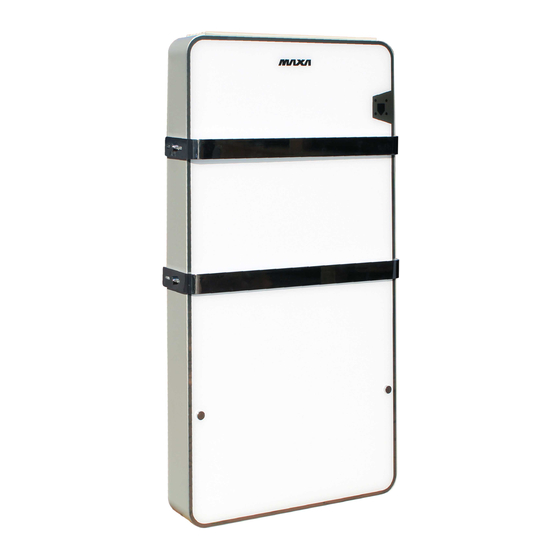
GRIMPER FAN BSL
MANUALE DI INSTALLAZIONE E USO
Installation AND OPERATING MANUAL
EINBAU- UND BEDIENUNGSANLEITUNG
MANUEL D'INSTALLATION ET MODE D'EMPLOI
MANUAL DE INSTALACIÓN Y USO
1
Advertisement
Table of Contents

Related Manuals for MAXA GRIMPER FAN Series


Summary of Contents for MAXA GRIMPER FAN Series
- Page 1 GRIMPER FAN BSL MANUALE DI INSTALLAZIONE E USO INSTALLATION AND OPERATING MANUAL EINBAU- UND BEDIENUNGSANLEITUNG MANUEL D’INSTALLATION ET MODE D’EMPLOI MANUAL DE INSTALACIÓN Y USO...
- Page 2 ATTENZIONE Leggere questo manuale accuratamente prima di usare l’apparecchio ed eseguire le operazioni come indicato. Le istruzioni sono importanti per la sicurezza e per un corretto funzionamento; accertarsi di osservarle. W ARN I NG Please read this manual carefully before using the equipment; carry well out all the operations here indicated.
- Page 3 INDEX INDEX INDICE - - INHALTSVERZEICHNIS - - INDICE 1. Premessa – Introduction – Einführung – Introduction -Introducción Identification of the unit Identification de l'unité Identificazione unità - - Kenndaten der Einheit - – Identificación de la unidad - Technical features Caractéristiques techniques 2.
- Page 4 INSTRUCTI ON I NTRODUCTI ON 1. PREMESSA - - EINFÜHRUNG – - INTRODUCCIÓN Congratulazioni per aver scelto un ventilconvettore GRIMPER FAN. La non osservanza di quanto qui descritto e/o una inadeguata installazione delle macchine, possono annullare la garanzia. Il costruttore, inoltre, non risponde di eventuali danni diretti e/o indiretti dovuti ad errate installazioni, e/o danni causati dalle unità installate da personale inesperto o non autorizzato.
- Page 5 Wir gratulieren Ihnen zur Wahl eines Gebläsekonvektors GRIMPER FAN. Das vorliegende Handbuch enthält die für Transport, Installation, Bedienung und Wartung der Einheiten erforderlichen Informationen. Die Missachtung der Anleitungen bzw. eine unsachgemäße Installation der Geräte können zum Verfall der vom Hersteller geleisteten Garantie führen. Der Hersteller haftet nicht für eventuelle direkte bzw. indirekte Schäden infolge falscher Installationen bzw.
- Page 6 Congratulaciones por elegir un ventilconvector GRIMPER FAN. Este manual presenta todas las informaciones utiles para el transporte, instalacion, uso y manutencion de las unidades. De no seguirse las instrucciones aqui descritas y/o en caso de una inadecuada instalacion de las unidades, el fabricante se reserva el derecho de anular la garantia.
- Page 7 I DENTI FI CATI ON OF THE UNI T IDENTIFICAZIONE UNITÀ - - KENNDATEN DER EINHEIT - I DENTI FI CATI ON DE L'UNI TE- IDENTIFICACIÓN DE LA UNIDAD Sur chaque unité GRIMPER FAN Le unità GRIMPER FAN Seitlich von den Geräten GRIMPER FAN units est apposée une plaquette Las unidades GRIMPER...
- Page 8 M AI N COM PONENTS COMPONENTI PRINCIPALI - - HAUPTBESTANDTEILE – COM POSANTES PR INCI P ALES - COMPONENTES PRINCIPALES Parti esterne – External parts – Außenteileb - Parties externes - Außenteile Right-hand side flank Panneau latéral droit Fianco laterale destro Rechtes Seitenteil Panel lateral derecho Left-hand side flank...
- Page 9 Parti interne – Internal parts – Interne Teile - Parties internes - Partes internas. Panels Panneau Pannelli Feld Panel Main heat-exchanger Echangeur principal Scambiatore principale Hauptwärmetauscher Batería principal Vaschetta raccolta Main condensate tray Kondensatwanne Bac à condensats Bandeja condensación condensa principale Fandeck Groupe ventilateur Ventilatore...
- Page 10 DATI TECNICI-TECHNICAL DATA-TECHNISCHE DATEN-DONNÉES TECNIQUES–DATOS TÉCNICOS Impianto a 2 tubi – 2 pipe system – 2 Leiter-System - I nstallation 2 tubes – Instalación 2 tubos REFROI DI SSEM EN T RAFFRESCAMENTO COOLI N G M ODE KÜHLBETRIEB ENFRIAMIENTO Ambiante:27 °C - 47 % HR T.ambiente:27 °C - 47 % UR , Room:27°...
- Page 11 Impianto a 2 tubi – 2 pipe system – 2 Leiter-System - I nstallation 2 tubes – Instalación 2 tubos HEIZUNG RISCALDAMENTO HEATI N G M ODE CHAUFFAGE CALEFACCIÓN Raumtemp.: 20°C Room:20° C. Temp. ambiante : 20 °C T.ambiente:20 °C, Temp.
- Page 12 Impianto a 4 tubi (**) – 4 pipe system (**) – 4 Leiter-System (**) - I nstallation 4 tubes (**) – Instalación 4 tubos (**) REFROI DI SSEM EN T COOLI N G M ODE RAFFRESCAMENTO KÜHLBETRIEB ENFRIAMIENTO Ambiante:27 °C - 47 % HR Room:27°...
- Page 13 Impianto a 4 tubi (**) – 4 pipe system (**) – 4 Leiter-System (**) - I nstallation 4 tubes (**) – Instalación 4 tubos (**) HEIZUNG HEATI N G M ODE CHAUFFAGE RISCALDAMENTO CALEFACCIÓN Raumtemp.: 20°C T.ambiente:20 °C, Room:20° C. Temp.
- Page 14 BSL12 Numero ranghi scambiatore principale Number of rows of main coil Reihenzahl Hauptregister Nombre de rangées de la batterie principale Número rangos batería principal Coil connection Connexions de la batteri Attacchi batteria – Batterieverbindungen - 3/4“ GM - Conexiones de la batería Supermax V/H/Ph 230 V –...
- Page 15 DATI DI RUMOROSITA’ - NOI SE LEVEL DATA - LÄRMBELASTUNG - DON NEES B RUI T – NIVEL DE RUIDO Potenza sonora - Sound pow er - Schallleistung - Puissance Pressione sonora - Sound pressare acoustique P ression acoustique Potencia sonora Schalldruck - Presión sonora DC SERIES...
- Page 16 DIMENSIONI E PESI – DI M ENSI ONS AND W EI GHTS – ABMESSUNGEN UND GEWICHTE – DI M ENSI ONS ET P OI DS - DIMENSIONES Y PESOS Le connessioni idrauliche sono sempre sul lato destro. La scatola elettrica è sul lato opposto. Hydraulic connections only in the right side.
- Page 17 I NSTALLATI ON I NSTR UCTI ONS 3. ISTRUZIONI PER L’INSTALLAZIONE - INSTALLATIONSANWEISUNGEN - I NSTR UCTI ONS POUR L’INSTALLATI ON INSTRUCCIONES PARA LA INSTALACIÓN W AR NI NGS AVERTI SSEM ENTS- AVVERTENZE - - WICHTIGE HINWEISE – ADVERTENCIAS Unità per installazione all'interno. Per la movimentazione delle unità...
- Page 18 Unitè pour installation à l'interieur. Pour la manutention des unités, utiliser des appareils ou engins de levage appropriés conformément aux dispositions de la directive 2007/30/CEE et modificatifs Le constructeur décline toute responsabilité en cas de non-respect des règles de sécurité et de prévention suivantes. La responsabilité...
- Page 19 POSIZIONAMENTO DELL’UNITÀ - P OSI TI ON I N G OF THE UNI T - POSITIONIERUNG DER EINHEIT - EM P LACEM ENT DE L'UN I TE - POSICIONAMIENTO DE LA UNIDAD. Posizionare l’unità su di una struttura idonea a sopportare il peso della macchina. Si consiglia di utilizzare sistemi antivibranti, tali da impedire la trasmissione delle vibrazioni alla struttura stessa.
- Page 20 RIMOZIONE DEL PANNELLO FRONTALE REM OVAL OF THE FRON TAL PAN EL ENTFERNUNG DER FRONTSEITE RETRAI T DE LA FACE AVAN T DESMONTAJE DEL PANEL FRONTAL Rimuovere le n.4 coperture delle viti su ciascun lato per staccare le maniglie porta salviette.
- Page 21 Rimuovere le viti come indicato nell’immagine a sinistra. Fare molta attenzione a non danneggiare il pannello in vetro e avere particolare cura di non stringere troppo le viti quando si riposizionerà lo stesso pannello. Usare un cacciavite e non l’avvitatore. Nel caso ci siano delle viti in plastica, ricordarsi la posizione in modo da riposizionarle nella stessa posizione quando si rimonta il pannello.
- Page 22 REM OVAL OF THE M ETAL FLANK S ENTFERNEN DER SEITENWÄNDE AUS METAL ÉLI M I NATI ON DES P AR TI ES M ÉTALLI QUES LA ELIMINACIÓN DE LAS PARTES METÁLICAS Rimuovere il pannello frontale come indicato nelle sezioni precenti. Remove the frontal panel how shown in the previous sections.
- Page 23 Procedere alla rimozione del fianco destro come indicato nell’immagine alla sinistra. Remove the right metal flank as indicated in the image on the left. Entfernen Sie die rechte Metallflanke wie in der Abbildung links gezeigt. Retirez le flanc métallique droit comme indiqué sur l'image de gauche.
- Page 24 ACCESSO ALLA SCHEDA ELETTRONICA E ALLE PARTI INTERNE (VENTILATORE, VASCHETTA RACCOLTA CONDENSA PRINCIPALE E AUSILIARIA E BATTERIA). ACCESS TO THE M AI N ELECTRONI C BOARD AN D TO THE I NTERNAL P ARTS (FAN M OTOR, M AI N AND AUX I LI ARY DRAI N P AN AND W ATER COI L).
- Page 25 Procedere con la rimozione del pannello in metallo. Proceed with the metal panel removal. Fahren Sie mit dem Entfernen der Metallplatte fort. Procédez à l'enlèvement du panneau métallique. Continuar con la extracción del panel de metal. Fan motor Ventilateur (1) Ventilatore – - Fan-Motor –...
- Page 26 Per rimuovere la copertura e accedere alla scheda elettronica, alzare la stessa copertura come indicato dalla freccia nella figura alla destra. To remove the cover and access to main PCB, move up the same cover as shown in the picture on the left. Um die Abdeckung abzunehmen und auf die elektronische Hauptplatine zuzugreifen, schieben Sie dieselbe Abdeckung nach oben, wie in der Abbildung links gezeigt.
- Page 27 FISSAGGIO DELL’UNITÀ - FI X I NG THE UNI T BEFESTIGUNG DER EINHEIT - FI X ATI ON DE L'UNI TE - FIJACIÓN DE LA UNIDAD Predisporre le forature secondo le quote della figura sopra. Fissare quattro tiranti filettati M6. Nota: assieme all’unità...
- Page 28 HYDRAULI C CONN ECTI ONS COLLEGAMENTI IDRAULICI - -WASSERANSCHLÜSSE – CONNECTI ONS HYDRAULI QUES - CONEXIONES HIDRÁULICAS Gli scambiatori delle unità sono forniti di attacchi filettati gas 3/4“ GM. La pressione massima di esercizio delle batterie non deve superare i 6 bar Rispettare le indicazioni poste sul fianco delle unità...
- Page 29 Hydraulic connections pipe Tubazioni per collegamento – – Hydraulikanschlussleitung – Tuyau de raccordem ent hydraulique - Tubería de conexiones hidráulicas. Φ acciaio (”) Φ rame (mm) Φ multistrato (mm) Φ Steel (”) Φ copper (mm) Φ multilayer pipe (mm) Φ stehlen (”) Φ...
- Page 30 COLLEGAMENTI ELETTRICI - ELECTR I CAL CONN ECTI ONS - ELEKTRISCHE ANSCHLÜSSE - RACCORDEM ENTS ÉLECTRI QUES - CONEXIONES ELÉCTRICAS Prima di iniziare qualsiasi operazione assicurarsi che la linea di alimentazione generale sia sezionata. Before starting any work on the appliance make sure the main electrical power supply line has been disconnected. Bevor Sie mit irgendeiner Operation beginnen, müssen Sie sicherstellen, dass die allgemeine Stromzuleitung unterbrochen ist.
- Page 31 4. SCHEMI ELETTRICI - W I RI NG DI AGR AM S - SCHALTBILDER - SCHÉM AS ÉLECTRIQUES - DIAGRAMAS ELÉCTRICOS Ci sono due modi per controllare le unità: Telecomando. Termostato remoto da posizionare a muro, in un adeguato posto e ad un’altezza di circa 1,5m dal pavimento. Tutti gli schemi elettrici riportati nella sezione successiva, fanno riferimento a un impianto a 2 tubi.
- Page 32 I nfrared hanset rem ote control Télécom m ande Telecomando - . – Fernsteuerung – - Mando a distancia...
- Page 33 Using a rem ote therm ostat o be positioned on the w all Termostato remoto da posizionare a muro - À l’aide d’un therm ostat à distance, placez-vous sur le m ur Verwenden Sie einen Fernthermostat - Utilice un termostato remoto para colocarlo en la pared...
- Page 35 Dip sw itch setting for RP M Réglage du Settaggi dip switch per giri motore – - DIP-Schalter für RPM - com m utateur DI P pour RP M - Ajuste del interruptor DIP para RPM...
- Page 36 M AI NTENANCE AND CHECK S 5. MANUTENZIONI E CONTROLLI – - WARTUNG UND ENTRETIEN ET CONTR ÔLES KONTROLLEN - – MANUTENCIÓN Y CONTROLES Verificare periodicamente che la batteria di scambio termico sia pulita. Verificare il serraggio di viti, bulloni, connessioni idriche ed elettriche, che potrebbero essersi allentate in conseguenza delle vibrazioni indotte dal funzionamento della macchina.
- Page 37 FAULT FINDING - P ROBLEM BEHANDLUNGSVER FAHR EN - 6. PROCEDURA GUASTI – DEP ANNAGE – BÚSQUEDA DE AVERÍ AS Fare eseguire i controlli necessari solo a personale qualificato Ensure that the various checks and inspections are performed exclusively by appropriately qualified personnel Lassen Sie die erforderlichen Kontrollen nur durch Fachpersonal durchführen.
- Page 38 7. ISTRUZIONI INSTALLAZIONE ACCESSORI / ACCESSORIES INSTR UCTI ONS / ANLEITUNG ZUM ZUBEHÖR / INSTR UCTI ONS ACCESSOIR ES / INSTRUCCIONES DE ACCESORIOS STSL La sonda acqua viene usata come termostato di minima e di massima e va posizionata dall’installatore sul pozzetto dello scambiatore, a ridosso di un tubo il più...
- Page 39 2V2BSL...
- Page 40 3V2BSL...
- Page 41 3V2BSL, 2V2BSL VALVE WITH MICRO VERSION - VANNE AVEC MICRO VALVOLA CON MICRO - VENTIL MIT MIKRO – - VÁLVULA CON MICRO...
- Page 42 Tem plate M odèles Dima di riscontro / / Vorlagen / / Plantillas. Minimum distance to ceiling 200mm - Use metal anchor to fix machine to the wall Min. Min. 80mm 80mm 1100 Plumbing and wiring connection from wall Drainage pipe Minimum distance to floor 200mm...
- Page 44 ADVANTIX SpA Via S. Giuseppe Lavoratore 24, 37040 Arcole (VR) Italy Tel. (+39).045.76.36.585 E-mail: info@advantixspa.it www.maxa.it...
Need help?
Do you have a question about the GRIMPER FAN Series and is the answer not in the manual?
Questions and answers