
Related Manuals for Vaillant VR 50


Summary of Contents for Vaillant VR 50
- Page 1 Operating and installation instructions Radiator thermostat VR 50 GB, IE Publisher/manufacturer Vaillant GmbH Berghauser Str. 40 D-42859 Remscheid Tel. +49 21 91 18-0 Fax +49 21 91 18-2810 info@vaillant.de www.vaillant.de...
-
Page 2: Table Of Contents
Contents Contents Safety ................4 Action-related warnings ..........4 1.2 Intended use ..............5 1.3 General safety information ......... 7 Notes on the documentation ........9 2.1 Observing other applicable documents ....9 2.2 Storing documents ............9 2.3 Validity of the instructions .........9 System and product description ......10 3.1 Component of the ambiSENSE system ....10 3.2 Design of the product ..........12 3.3 Display ................13... - Page 3 Contents 5.2 Installing the radiator thermostat with Danfoss adapter ................27 5.3 Installing the radiator thermostat with support ring ..................32 Start-up ................33 6.1 Adaptive run ..............33 Operation ..............34 Changing the operating mode .........34 7.2 Setting the temperature ..........34 7.3 Using the Boost function ...........35 7.4 Activating/deactivating the operation lock ..36 Troubleshooting ............36 8.1 Command not confirmed ...........36...
-
Page 4: Safety
Safety Safety Action-related warnings Classification of action-related warnings The action-related warnings are classified in accordance with the severity of the pos- sible danger using the following warning signs and signal words: Warning symbols and signal words Danger! Imminent danger to life or risk of severe personal injury Danger! Risk of death from electric... -
Page 5: Intended Use
Safety Caution. Risk of material or environmental damage Intended use In the event of inappropriate or improper use, damage to the product and other property may arise. You can use the radiator thermostat for the time-controlled regulation of common radiator valves from the following manu- facturers: –... - Page 6 Safety – Watts – Wingenroth (Wiroflex) – R.B.M – Tiemme – Jaga – Siemens – Idmar Intended use includes the following: – observance of accompanying operating, installation and servicing instructions for the product and any other system components – installing and fitting the product in accordance with the product and sys- tem approval –...
-
Page 7: General Safety Information
Safety in this document shall be considered improper use. Any direct commercial or industrial use is also deemed to be improper. Caution. Improper use of any kind is prohibited. General safety information 1.3.1 Danger caused by improper operation Improper operation may present a danger to you and others, and cause material damage. - Page 8 Safety 1.3.2 Risk of material damage caused by frost > Do not install the product in rooms prone to frost. 1.3.3 Risk of material damage caused by unsuitable environmental conditions. The electronics may be damaged if you install the product in an unsuitable envi- ronment.
-
Page 9: Notes On The Documentation
Storing documents > Keep this manual and all other applica- ble documents safe for future use. Validity of the instructions These instructions apply only to: Product article number VR 50 0020247920 VR 50 0020242487 Operating and installation instructions 0020248967_00... -
Page 10: System And Product Description
System and product description System and product description Component of the ambiSENSE system The product is part of the ambiSENSE room climate solution and communicates with the VR 920 Internet gateway via a radio protocol. All products in the ambiSENSE room climate solution can be configured using the VRC 700 app on a smartphone. - Page 11 System and product description You manually start the pairing mode for three minutes by briefly pressing the sys- tem button. The product is suitable for all common radiator valves with thread dimensions of M30 x 1.5 mm. Using the adapter that is included in the scope of delivery means that the product can also be installed on Danfoss RA, Danfoss RAV and Danfoss...
-
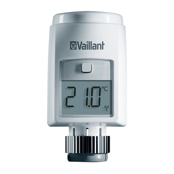
Page 12: Design Of The Product
System and product description Design of the product Knurled nut 2 Display 3 System button with signal LED 4 Battery compartment 5 Setting wheel Operating and installation instructions 0020248967_00... -
Page 13: Display
System and product description Display Note The background lighting for the dis- play is switched off in Standby mode. To activate the background lighting, press the setting wheel once. VALVE install VALVE adapt MANU BOOST Operation lock active 2 Automatic decrease active Operating and installation instructions 0020248967_00... -
Page 14: Window-Opening Detector
System and product description 3 Radio data transmission 4 Low battery charge 5 Boost mode active 6 Manual mode active 7 Target temperature °C 8 Status information for the valve Window-opening detector When a window is open, e.g. for ventila- tion, the system automatically lowers the temperature in order to save heating energy and costs. -
Page 15: Radio Operation
System and product description Radio operation The radio signal is transmitted on a non-exclusive transmission path. Faults can therefore not be ruled out. Interfer- ences may, for example, be caused by switching operations, electric motors or defective electrical units. The range inside buildings may differ con- siderably from the range outdoors. -
Page 16: Flashing Sequence Of The Signal Led
System and product description Flashing sequence of the signal LED Flashing Required Meaning sequence activity Brief period Radio trans- Wait until the of flashing mission/ transmission orange transmission has ended. attempt/data transmission 1 x long Process con- Continue with period of firmed the opera- lighting up... - Page 17 System and product description Flashing Required Meaning sequence activity Brief period Batteries flat Replace the of lighting up batteries. orange (after a green or red reception notification) 3 x long Product Note the dis- period of defective play in the flashing red App or con- tact the spe-...
-
Page 18: Duty Cycle Limit
System and product description Flashing Required Meaning sequence activity Long and Update to the New software brief period unit software is trans- of flashing (OTAU = Over ferred. (Dura- orange (alter- the Air tion: Up to 12 nating) Update) hours) This does not affect how the product... -
Page 19: Ce Marking
System and product description 1 hour). The product complies with this directive. In normal mode, the duty cycle limit is not normally reached. In individual cases, e.g. during start-up or the new installation of a system, increased and radio-intensive pair- ing processes may mean that this limit is not reached. -
Page 20: Checking The Scope Of Delivery
Direc- tive 2014/53/EU. The complete text for the EU Declaration of Conformity is available at: http://www.vaillant-group.com/doc/ doc-radio-equipment-directive/. Checking the scope of delivery > Check that the scope of delivery is com- plete and intact. -
Page 21: Integration Into The Ambisense System
Integration into the ambiSENSE system Number Designation Unit number sticker (SGTIN = Serialised Global Trade Item Number) Operating and installation instructions Integration into the ambiSENSE system Pairing To ensure that the product is integrated into the ambiSENSE system and can com- municate with other ambiSENSE units, it must first be paired to the VR 920 Internet gateway. - Page 22 Integration into the ambiSENSE system > Open the VRC 700 app on the smart- phone. > Select Settings on the bottom right. > Select ambiSENSE > Select Add individual room compo- nent. > Follow the installation assistant. > When the installation assistant in the app requests that you establish the power supply, open the product’s bat- tery compartment and pull the insulat-...
- Page 23 Integration into the ambiSENSE system the app to confirm. Alternatively, use the smartphone to scan the QR code. Note You can find the unit number and the QR code on the enclosed sticker and in the product’s battery com- partment. >...
-
Page 24: Set-Up
Set-up Set-up Installing the radiator thermostat 1. Turn the thermostat head anti-clockwise to the maximum value. – The thermostat head is now no longer pushing against the valve Operating and installation instructions 0020248967_00... - Page 25 Set-up spindle and can therefore be removed more easily. 2. Remove the thermostat head from the radiator valve. Conditions: Fastening with union nuts > Loosen the union nuts in an anti-clock- wise direction and remove the thermo- stat head. Conditions: Fastening with snap-on mounts >...
- Page 26 Set-up Conditions: Fixing with set screws > Undo the set screw and remove the thermostat head. 3. Start the pairing process in the App. (Page 4) 4. Install the product when you are requested to do so in the App during the pairing process.
-
Page 27: Installing The Radiator Thermostat With Danfoss Adapter
Set-up 6. Use the knurled nut on the radiator valve to install the new radiator thermo- stat. Installing the radiator thermostat with Danfoss adapter 1. Remove the old thermostat head from the radiator valve. Operating and installation instructions 0020248967_00... - Page 28 Set-up 2. In each case, use the enclosed adapter for the installation on Danfoss radiator valves. Conditions: Danfoss RA radiator valve > During the installation, ensure that the pins inside the adapter (2) are congru- ent to the recesses (1) on the valve. >...
- Page 29 Set-up > Use the enclosed screw and nut to secure the adapter. Conditions: Danfoss RAV radiator valve > Before the installation, mount the tap- pet extension (2) onto the valve pin. > During the installation, ensure that the pins inside the adapter (3) are congru- ent to the recesses (1) on the valve.
- Page 30 Set-up > Snap the adapter that is suitable for the valve fully into place. > Use the enclosed screw and nut to secure the adapter. Conditions: Danfoss RAVL radiator valve > During the installation, ensure that the pins inside the adapter (2) are congru- ent to the recesses (1) on the valve.
- Page 31 Set-up > Snap the adapter that is suitable for the valve fully into place. Note The RAVL adapter is not screwed 3. Use the knurled nut on the adapter to install the new radiator thermostat. Operating and installation instructions 0020248967_00...
-
Page 32: Installing The Radiator Thermostat With Support Ring
Set-up Installing the radiator thermostat with support ring > If the diameter of the part of the radia- tor valve that projects into the radiator thermostat is too small, place the sup- port ring (1) into the flange before installation. Operating and installation instructions 0020248967_00... -
Page 33: Start-Up
Start-up Start-up Adaptive run An adaptive run (Valve adapt) must be carried out after the installation. > If Valve adapt is shown in the display, start the adaptive run by pressing the setting wheel. – During the adaptive run, Valve adapt is shown on the display. -
Page 34: Operation
Operation Operation Changing the operating mode Automatic mode: The heating programme that is set via the VRC 700 app is active. Manual mode: You can set the temperature on the product or by using the VRC 700 app. The temperature setting is retained until the next time a manual change is implemented. -
Page 35: Using The Boost Function
Operation the current time programme for a certain amount of time. The duration for which the manually set temperature should apply can be individually defined here. In manual mode, the temperature is retained until the next time a manual change is implemented. >... -
Page 36: Activating/Deactivating The Operation Lock
Troubleshooting Activating/deactivating the operation lock You can use the relevant room settings in the VRC 700 app to activate and deacti- vate the product‘s operation lock. Troubleshooting Command not confirmed If at least one transceiver does not con- firm a command, the signal LED lights up red once the incorrect transmission is completed. -
Page 37: Fault Messages
Troubleshooting Fault messages If a fault occurs, a fault code Fx. is shown in the display instead of the temperature display. Fault Possible Remedy cause Valve drive Check whether the stiff tappet for the heat- ing valve is jammed. Setting range Check the fastening too big for the radiator... -
Page 38: Resetting To Factory Setting
Troubleshooting Communica- Check the connec- tion fault to tion to the Internet the Internet gateway and/or to gateway and/ the repeater. flashes or to the repeater Resetting to factory setting Note All settings will be lost. 1. Remove the batteries. (Page 41) Operating and installation instructions 0020248967_00... - Page 39 Troubleshooting 2. Re-insert the batteries in accordance with the polarity markings and, at the same time, press and hold the system button for four seconds until the signal LED starts to rapidly flash in orange. 3. Release the system button. 4.
-
Page 40: Care And Maintenance
Care and maintenance 5. Release the system button. – The product restarts. Care and maintenance Caring for the product > Clean the casing with a damp cloth and a little solvent-free soap. Operating and installation instructions 0020248967_00... -
Page 41: Changing Batteries
Care and maintenance Changing batteries 1. Open the battery compartment as shown in the figure. 2. Always change all the batteries at the same time. – Battery type: LR06/Mignon/AA 3. Do not use rechargeable batteries. Operating and installation instructions 0020248967_00... - Page 42 Care and maintenance 4. Insert the batteries, making sure that the poles are the right way round. – After inserting the batteries, the product runs through a self-test for approx. two seconds. Initialisation then takes place. 5. After inserting the batteries, observe the flashing sequence of the signal LED.
- Page 43 Care and maintenance – Self-test successful: Signal LED lights up orange first and then green. > Close the battery compartment. 9.2.1 Risk of death caused by unsuitable batteries Danger! Risk of death caused by unsuitable batteries! If batteries are replaced with the wrong type of battery, there is a risk of explosion.
- Page 44 Care and maintenance > Ensure that you use the cor- rect battery type when replacing batteries. > Dispose of used batteries in accordance with the instruc- tions in this manual. 9.2.2 Leaking batteries Danger! Risk of chemical burns caused by leaking batteries! If the product is not used for sev- eral weeks, the batteries may leak.
- Page 45 Care and maintenance > Remove the batteries if you will be away for an extended period. > Take suitable measures to protect against chemical burns (e.g. wear protective gloves). 9.2.3 Batteries > Note the battery type, as described in these instructions; see section “Data plate”.
-
Page 46: 10 Decommissioning
Decommissioning > Insert the batteries, making sure that the poles are the right way round. > Remove the dead batteries from the product and dispose of them correctly. > Remove the batteries if you intend to store the product and not use it for an extended period and/or to scrap it. -
Page 47: 10.2 Recycling And Disposal
Customer service 10.2 Recycling and disposal If the product is labelled with this mark: > In this case, do not dispose of the prod- uct with the household waste. > Instead, hand in the product to a collec- tion centre for old electrical or elec- tronic appliances. -
Page 48: 12 Technical Data
Technical data 12 Technical data Parameter Value Battery type 2 x 1.5 V LR6/ Mignon/AA 120 mA Current consumption Battery life 2 years IP rating IP 20 Degree of contamina- tion Permissible 0 … 50 °C environmental temperature Height 71 mm (2.80 in) Width 58 mm (2.28 in) - Page 49 Technical data Parameter Value Maximum transmission < 25 mW power Receiver category SRD category 2 Range outdoors 300 m (984 ft - 3 in) Duty Cycle < 1% per h / < 10% per h Mode of operation Typ 1 Connection M30 x 1,5 mm Operating and installation instructions 0020248967_00...
- Page 52 0020248967_00 Supplier Vaillant Ltd. Nottingham Road Belper Derbyshire DE56 1JT Telephone 0330 100 3461 info@vaillant.co.uk www.vaillant.co.uk © These instructions, or parts thereof, are protected by copyright and may be reproduced or distributed only with the manufacturer's written consent. We reserve the right to make technical changes.
Need help?
Do you have a question about the VR 50 and is the answer not in the manual?
Questions and answers