Table of Contents
Advertisement
INSTALLATION AND
OPERATION MANUAL
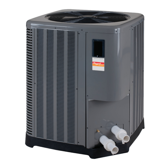
Heat Pump Pool &
Spa Heater
Models 2450, 3450, 4450,
5450, 6450, 6450PD, 6450HC,
8450 & 8450HC
FOR YOUR SAFETY: Do not store or use gasoline or other flammable vapors and
liquids or other combustible materials in the vicinity of this or any other appliance.
To do so may result in an explosion or fire.
NOTE: The instructions in this manual are for the use of qualified individuals specially trained and experienced
in the installation and maintenance of this type of equipment and related system components. Installation and
service personnel are required by some states to be licensed. Persons not qualified shall not attempt to install,
service, or maintain this equipment.
This manual should be maintained in legible condition and kept adjacent to the heat pump pool heater or in a
safe place for future use.
Effective: 11-20-20
Replaces: Catalog# 6000.56
P/N 241909 Rev. 1
Advertisement
Chapters
Table of Contents

Related Manuals for Rheem Raypak 2450


Summary of Contents for Rheem Raypak 2450
- Page 1 INSTALLATION AND OPERATION MANUAL Heat Pump Pool & Spa Heater Models 2450, 3450, 4450, 5450, 6450, 6450PD, 6450HC, 8450 & 8450HC FOR YOUR SAFETY: Do not store or use gasoline or other flammable vapors and liquids or other combustible materials in the vicinity of this or any other appliance. To do so may result in an explosion or fire.
- Page 2 Revision 1 reflects the following changes: Formatting updated throughout. Introduction text revised on page 5. Illustrated Parts list added on page 48.
-
Page 3: Table Of Contents
CONTENTS 1. WARNINGS ............4 High Pressure Switch Lockout ......33 Low Pressure Switch Lockout ....... 33 Pay Attention to these Terms ........4 Water Pressure Switch .......... 33 2. INTRODUCTION ............. 5 Sequence of Operation ......... 33 3. WATER CHEMISTRY ..........6 14. -
Page 4: Warnings
1. WARNINGS Pay Attention to these Terms Indicates the presence of immediate hazards which will cause severe personal injury, death or substantial DANGER property damage if ignored. ndicates the presence of hazards or unsafe practices which could cause severe personal injury, death or WARNING substantial property damage if ignored. -
Page 5: Introduction
• physical address of where the unit is installed; please 2. INTRODUCTION include any ‘subdivision’ or similar information • any service challenges present at the house/ WARNING: This heat pump pool heater is an neighborhood: gated community, locked access at electromechanical machine that... -
Page 6: Water Chemistry
3. WATER CHEMISTRY Situate the heater carefully to minimize installation costs while providing maximum efficiency of operation, and to allow adequate service access, as follows: (Corrosive water voids all warranties) • For unrestricted air intake and service access, For your health and the protection of your pool equipment, position each side of the unit at least 1 ft (30 cm) it is essential that your water be chemically balanced. - Page 7 60” (1.52m) MIN 3 FT AIR FLOW OUT (09.m) 12” (0.3m) FLOW FLOW HEATER Figure 2. Installation Clearances • When installed in areas where freezing temperatures can be encountered, drain the water circuit to prevent possible freeze-up damage. Refer to "Freeze Protection"...
- Page 8 Figure 4. Hurricane Tie Down Instructions – 2450...
- Page 9 Figure 5. Hurricane Tie Down Instructions – 3450 - 4450...
- Page 10 Figure 6. Hurricane Tie Down Instructions – 5450 - 8450...
-
Page 11: Electrical Connections
5. ELECTRICAL 6. WATER CONNECTIONS CONNECTIONS CAUTION: The heater inlet and outlet connections are NOT interchangeable. They must be connected as Refer to the unit rating plate below the control panel for instructed below. precise power requirements for your unit, and for ampacity and over-current protection requirements. -
Page 12: Pressure Drop
Please note that some municipalities do not allow the use 7. PRESSURE DROP of a shutoff valve on the effluent/outlet side of any heating equipment, especially when there is one on the inlet side. For system pressure drop information, see Table B. These entities typically instead allow a PVC tee and spring Pressure Drop (PSI) Flow... -
Page 13: User Modes
If the membrane switch remains inactive for 180 seconds 9. USER MODES (3 minutes), the screen will revert to the current view. For HEAT ONLY and POWER DEFROST models, the On HEAT ONLY and POWER DEFROST models, the mode selections are: options available by pressing the MENU/SET (MENU) button are POOL HEAT, SPA, TIMED SPA and OFF. -
Page 14: Control Menus
3. When POOL AUTO mode is selected, each press of The INSTALLER/SERVICE menu can be accessed by the UP or DOWN buttons will increase / decrease pressing and holding the UP and MENU buttons for 3+ the pool setpoint temperature. Holding the UP or seconds. -
Page 15: User Menu - Heat Only, Power Defrost And Heat/Cool Models
User Menu – Heat Only, Power Defrost and Heat/Cool Models NOTE: The User Menu is exactly the same for Heat ONLY, Power Defrost and Heat/Cool models. NOTE: Make sure that the values for each setting are recorded for future reference or if the control ever needs to be reset to Factory Defaults. - Page 16 Default Access Item Range Description Value Level Return Valve 2 Pool/Spa Pool User Select the position of a 3-way valve located between the heater and the Pool/Spa for this scheduled pump period. Suction Valve 2 Pool/Spa Pool User Select the position of the 3-way valve located between the Pool/Spa and the Pump for this scheduled pump period.
-
Page 17: Installer/Service Menu - Heat Only Configuration
Installer/Service Menu – Heat Only Configuration The Installer/Service menu is used by Installers and Service personnel to set up and troubleshoot the heater. This menu is accessed by pressing and holding the UP and MENU buttons for 3+ seconds. WARNING: This menu should never be used by the end user as changes can affect proper operation of the unit. - Page 18 Default Access Item Range Description Value Level Pump Off Time 3 12:00A–11:59P Installer Select OFF time for Pump Period #3 to stop. On 4-speed pumps, this denotes the selected 1–4 if 4-Speed pump output (which connects to the pump for Enabled the selected speed) for this pump period.
- Page 19 Default Access Item Range Description Value Level Voltage Press UP or DOWN buttons to access Installer/ Up/ Down additional temperature measurements. Service for More Installer/ Displays the 24VAC voltage as measured by Voltage View Only – VAC the control board. Service Displays the coil temperature sensor value –...
- Page 20 Default Access Item Range Description Value Level Installer/ This is the temperature measured on the coil 20°F–35°F 24°F Service when the control goes into Defrost mode. Defrost Temp (-6.5°C–1.5°C) (-4°C) Sub- menu Installer/ Defrost terminates when the coil temperature Defrost 5°F–20°F 10°F Service...
-
Page 21: Installer/Service Menu - Power Defrost Configuration
Installer/Service Menu – Power Defrost Configuration NOTE: Make sure that the values for each setting are recorded for future reference or if the control ever needs to be reset to Factory Defaults. All these values will need to be re-entered. Default Access Item... -
Page 22: Pump On Time
Default Access Item Range Description Value Level Pump Off Time 3 12:00A–11:59P Installer Select OFF time for Pump Period #3 to stop. On 4-speed pumps, this denotes the selected 1–4 if 4-Speed pump output (which connects to the pump for Enabled the selected speed) for this pump period. -
Page 23: Return Valve
Default Access Item Range Description Value Level Voltage Press UP or DOWN buttons to access additional Installer/ Up/ Down temperature measurements. Service for More Installer/ Displays the 24VAC voltage as measured by the Voltage View Only – VAC Service control board. Displays the coil temperature sensor value –... - Page 24 Default Access Item Range Description Value Level Installer/ Select ON time for AUX1 to take effect. Service AUX1 On Time 12:00A-11:59P Sub- menu Installer/ Select OFF time for AUX1 to stop. Service AUX1 Off Time 12:00A-11:59P Sub- menu Installer/ Select ON time for AUX2 to take effect. Service AUX2 On Time 12:00A-11:59P...
-
Page 25: Installer/Service Menu - Heat/Cool Configuration
Installer/Service Menu – Heat/Cool Configuration NOTE: Make sure that the values for each setting are recorded for future reference or if the control ever needs to be reset to Factory Defaults. All these values will need to be re-entered. Default Access Item Range... -
Page 26: Pump On Time
Default Access Item Range Description Value Level Pump Off Time 3 12:00A–11:59P Installer Select OFF time for Pump Period #3 to stop. On 4-speed pumps, this denotes the selected 1–4 if 4-Speed pump output (which connects to the pump for Enabled the selected speed) for this pump period. -
Page 27: Return Valve
Default Access Item Range Description Value Level Voltage Press UP or DOWN buttons to access Installer/ Up/ Down additional temperature measurements. Service for More Displays the 24VAC voltage as measured by Installer/ Voltage View Only – VAC the control board. Service View Only –... - Page 28 Default Item Range Access Level Description Value Installer/ AUX1 On 12:00A-11:59P Service Select ON time for AUX1 to take effect. Time Sub-menu Installer/ AUX1 Off 12:00A-11:59P Service Select OFF time for AUX1 to stop. Time Sub-menu Installer/ AUX2 On 12:00A-11:59P Service Select ON time for AUX2 to take effect.
-
Page 29: Control Settings
11. CONTROL SETTINGS 12. TEMPERATURE CONTROL The user can access these control settings by pressing The control uses the appropriate Pool or Spa setpoint as and holding the MENU button for 5+ seconds. selected in the Operating mode. The heat demand begins changes to values are stored into the non-volatile memory when the water temperature is 0.5°F (0.3°C) or more when the MENU button is pressed –... -
Page 30: Aux Mode
value and press the MENU button to lock in that value. Heat Pump Pool Heater can provide on its own, The cursor moves to the next digit for setting. Once the during a given time and/or outside conditions, in last digit is selected (pressing MENU) the display will ask order to be achieved within the operator’s desired to confirm the established Lockout code. -
Page 31: Pool Heat Mode
the UP and DOWN buttons for 3 seconds to exit REMOTE duration of spa heating (up to a maximum duration of Mode. 6 hours in 15-minute increments). On HEAT/COOL models, the control displays “Remote 3. The timer will start to count down from the selected Pool”... -
Page 32: Defrost Operation
heat, pool heat or pool cool AND when Pump operation Defrost Operation is enabled through the control. This takes priority over The control is equipped with several defrost algorithms positions requested by Pump Schedule operations. If the depending on the configuration of the unit (HEAT ONLY, control also operates the pump, the pump will shut off POWER DEFROST or HEAT/COOL). -
Page 33: High Pressure Switch Lockout
5. Upon initial installation, there are several items that High Pressure Switch Lockout must be defined and programmed depending on If the high pressure switch opens, the control de-energizes the configuration and accessories intended to be the compressor output and the fan continues to run for 15 controlled by the heater control. -
Page 34: Digital Controls Operating Instructions
be 8°–10°F (4.4°–5.5°C) cooler than the air entering the Controls unit. Your heat pump pool heater incorporates digital safety When the unit has been operating in the cooling mode controls and indicators to ensure its safe, reliable for a few minutes, the discharge air temperature should operation. -
Page 35: Summer Shutdown
Continuous Pump Operation NOTE: If the pool pump and heat pump pool heater shut OFF before the water temperature is raised to the desired It is also possible in some areas to prevent unit freeze level, you must lengthen the running time of both. To do damage by operating the pump continuously during this, reset the time clock dial for the longer running time, or manually operate the pump with the timer override... -
Page 36: Troubleshooting
• Is the pool blanket/cover being used? Unblanketed pools can lose up to 10°F (5.5°C) per night compared to 4°F (2.2°C) or fewer when a blanket is used. Without a blanket, the total heat gained during the day can be lost overnight. DRAIN HOLES •... -
Page 37: Operational Status Messages
Troubleshooting Before troubleshooting the system, ensure that: • All mechanical and electrical connections are secure and tight • All system wiring is correct • Fuse is not blown (3A Automotive “ATO” type fuse for 24VAC) • That a system ground is properly connected to the heater. Nuisance shutdowns are often caused by a poor or erratic ground. -
Page 38: Error Messages
Error Messages The following error messages are displayed in Pool, Spa, and Remote modes. Consecutive identical faults are only stored once in the Fault History. Error Message Description Troubleshooting Amb Sensor Fail Ambient temperature sensor is OPEN or Replace Amb Temperature sensor. SHORTED. -
Page 39: Service Call Verification
22. SERVICE CALL Service Access to Heaters VERIFICATION If service access to the heater is required, it is accomplished by removing the control panel to provide a wide access NOTE: The Service number is located on the front of the to get to (1) compressor, (2) heat exchanger, (3) TXV, heater at the brand label. - Page 40 WARNING: If any wires have come off components during service of this unit, please refer to the wiring diagram on the back of the control panel cover or in the I&O manual to ensure that they are returned to the correct terminals/locations.
-
Page 41: Plumbing Diagrams
23. PLUMBING DIAGRAMS Figure 13. Plumbing Schematic – No External Bypass (Plumb the heater AFTER the filter and before any chlorinators.) - Page 42 Figure 14. Plumbing Schematic – External Bypass (Plumb the heater AFTER the filter and before any chlorinators.)
- Page 43 Figure 15. Piping for Heat Pump Pool Heater and Gas Pool Heater...
- Page 44 Figure 16. Piping for Multiple Heaters, Primary/Secondary...
-
Page 45: Wiring Diagram - 208V/230V Single-Phase - Digital Models
24. WIRING DIAGRAM – 208V/230V SINGLE-PHASE – DIGITAL MODELS BK (TO TRANSFORMER) VOLTAGE MONITOR INSERT A... -
Page 46: Installing A Remote Control Device
25. INSTALLING A REMOTE value established in the USER mode (HEAT/COOL models only). The control will use this value as the CONTROL DEVICE Heating setpoint and the Cooling Setpoint will be the SETPOINT + COOLING DEADBAND (established in the INSTALLER menu). 3. -
Page 47: Resistance Sensor Values
26. RESISTANCE SENSOR VALUES Other Sensors Water Sensor 10K Sensor Resistance Values 100K Sensor Resistance Values Temperature ºF (ºC) Resistance (Ω) Temperature ºF (ºC) Resistance (Ω) 32 (0) 32550 32 (0) ----- 41 (5) 25340 41 (5) 253950 50 (10) 19870 50 (10) 199040... -
Page 48: Illustrated Parts List
27. ILLUSTRATED PARTS LIST MODELS 2450-4450... - Page 49 CALL OUT DESCRIPTION 2450 3450 4450 CONTROLS TX Valve H000372 H000182 H000373 Low Pressure Switch H000078 H000078 H000078 High Pressure Switch H000079 H000079 H000079 Control Cover H000349 H000349 H000349 Temp Sensor 100K H000329 H000329 H000329 Ambient Temp Sensor H000332 H000332 H000332 Coil Sensor Coil Sensor Thermister 3/8"...
- Page 50 MODELS 5450-8450...
- Page 51 RAYPAK / RHEEM / RUUD CALLOUT DESCRIPTION 5450 6450 8450 CONTROLS TX Valve Heat H000173 H000173 H000077 Low Pressure Switch H000078 H000078 H000078 High Pressure Switch H000079 H000079 H000079 Control Cover H000349 H000349 H000349 Temperature Sensor 100K H000329 H000329 H000329...
- Page 52 NOTES...
- Page 53 NOTES...
- Page 54 ISO 9001 REGISTERED QUALITY MANAGEMENT SYSTEM www.raypak.com Raypak, Inc., 2151 Eastman Avenue, Oxnard, CA 93030 (805) 278-5300 Fax (805) 278-5468...
Need help?
Do you have a question about the Raypak 2450 and is the answer not in the manual?
Questions and answers
Hello - have a blank display on the LCD - was always very dim- up / down buttons work - IE: shut and turn off or on - unit heats great as always - Spent 3 hours on phone with your recommended reps ( 5) and received conflicting info - The question I need answered is : is there a separate display board other then the main computer board- 3 companies insisted there is none, 2 indicated that there is a separate display board. I do not want to hire a company that is going to install a 350$ main unit if only the display unit is malfunctioning. Thank you for any help - Michael
@michael sciarra
I have similar situation as Michael: After a contractor move my water heather to a new home, the display did not turn ON. I check voltage 220 VAC is OK, 24 VAC is ok, the internal fuse at mother board was not good, I install a new one. The display still off. Should be a problem in the Board or in the Display? Does any one recommend a test to know what is wrong? My Heather is Rheem 6450TI-E, with Display Densitron DH0116 Rev B
The heater display reads: COMP START DELAY
"COMP START DELAY" on a Rheem Raypak 2450 heater display means there is a 5-minute delay before the compressor starts operating again after it has turned off. This is a normal function to protect the compressor.
This answer is automatically generated