Table of Contents
Advertisement
Rheem Australia Pty Ltd
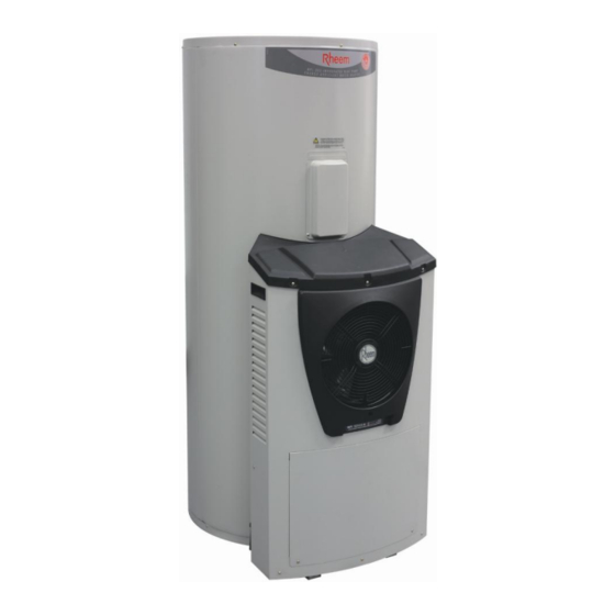
SERVICE INSTRUCTIONS
325 & 410 Series II Heat Pump
This document is stored and maintained electronically by
Solahart Everhot RheemPlus
325HAV
251325
251410
First Issued April 2014
554325
554410
Service. All printed copies are deemed uncontrolled.
ABN 21 098 823 511
TM077
Revision: 00
Issued: April 2014
Rheem
451325
551325
551410
Advertisement
Table of Contents

Related Manuals for Rheem 325 II Series


Summary of Contents for Rheem 325 II Series
- Page 1 Rheem Australia Pty Ltd ABN 21 098 823 511 SERVICE INSTRUCTIONS 325 & 410 Series II Heat Pump TM077 Revision: 00 Issued: April 2014 Solahart Everhot RheemPlus Rheem 325HAV 251325 554325 451325 251410 554410 551325 551410 First Issued April 2014 This document is stored and maintained electronically by Service.
-
Page 2: Table Of Contents
CONTENTS INTRODUCTION ......................... 3 SAFETY WARNING......................3 POWER SUPPLY ........................ 3 ENVIRONMENTAL ......................3 HEAT PUMP WATER HEATER MODEL IDENTIFICATION ..........4 HEAT PUMP WATER HEATER MODELS ................5 SPECIFICATIONS ....................... 6 PREVENTATIVE MAINTENANCE ..................8 REFRIGERATION TERMS AND THEIR MEANING ............9 COMPONENTS AND THEIR FUNCTION ................ -
Page 3: Introduction
During repair the refrigerant must always be recovered, never vented to the atmosphere. At the end of the service life of a Rheem heat pump, the refrigerant must be recovered by personnel qualified and licensed to work with refrigerants prior to the unit being disposed of. -
Page 4: Heat Pump Water Heater Model Identification
All identification numbers are designed to convey detailed information about the water heater to which it is attached. Model number, serial number and date of manufacture should be quoted in all correspondence. Rheem / Everhot Model Identification 2 – Everhot 4 – Rheem Optima 5 –... -
Page 5: Heat Pump Water Heater Models
04 or 18 = 1.8kW 05 or 24 = 2.4kW 07 or 36 = 3.6kW Heat Pump Brand Model Storage Tank Module 551325xx T551325xx Rheem 551410xx T551410xx Rheem Optima 451325xx T451325xx 182550 554325xx T554325xx RheemPlus 554410xx T554410xx 251325xx T251325xx Everhot 182553... -
Page 6: Specifications
SPECIFICATIONS Storage Tank Model T551325 T551410 Parameter T554325 1, 3 T554410 T451325 HP325S36 T251325 T251410 T325HAV Capacity (Litres) Boost Capacity (Litres) 100 / 180 Booster Element Rating (kW) 2.4 / 3.6 1.8 / 2.4 / 3.6 1.8 / 2.4 / 3.6 T&PR Valve Rating (kPa) 1000 1000... - Page 7 Heat Pump Module Model Parameter 182550 / 182553 / 182541 Superheat Setting (Factory) 6K at 10ºC saturated suction temperature Refrigerant Type R134a Refrigerant Charge 375 grams Cut Out: 2930kPa (± 103kPa) Refrigerant High Pressure Switch Manual Reset Pressure: 2241kPa (± 207kPa) Compressor Capacitor 25 µF +10/–5%, 370/440V AC, 50/60Hz Compressor Current Draw...
-
Page 8: Preventative Maintenance
PREVENTATIVE MAINTENANCE It is suggested that the water heater be serviced annually, to retain optimum performance. Annual Service Check for discharge from the T&PR valve. When the heat pump or element is operating a small discharge of water may be evident. Operate the valve, easing the lever to ensure the valve opens and reseats properly. -
Page 9: Refrigeration Terms And Their Meaning
REFRIGERATION TERMS AND THEIR MEANING Condense – The action of a substance as it releases heat and changes state from a vapour (gas) to a liquid. Evaporate – The action of a substance as it absorbs heat and changes state from a liquid to a vapour (gas). - Page 10 Evaporator – An aluminium finned copper coil where the low pressure, low temperature refrigerant absorbs heat from the surrounding ambient air. As the refrigerant absorbs heat and becomes warmer, it evaporates (changes state) to a saturated vapour. Heating of the saturated refrigerant vapour continues such that it becomes superheated.
-
Page 11: Controller
CONTROLLER Power and Tank Sensor Connections Sensors Four independent temperature sensors (thermistors) are utilised in the heat pump module. The sensors are identified as follows: Tank sensor Evaporator sensor Compressor sensor Heat exchanger water outlet sensor The sensors are monitored by the controller and provide information on specific temperatures. -
Page 12: Reset Button
Reset Button On the underside of the controller is a reset button. RESET BUTTON The reset button may be used to cancel the start delay, or reset Fault 9. Fault 9 will not disable all heating unless it has occurred 3 consecutive times however if Fault 9 has occurred once, or twice consecutively, the reset button will reset the consecutive occurrence count. -
Page 13: Operation
OPERATION The heat pump controller contains a main relay that ensures only the heat pump or the booster element can be operated. The main relay will enable element operation in its un- powered (off) state. Whenever power is available and element heating is not being used, the controller energises the main relay to enable heat pump operation. - Page 14 SYSTEM START-UP When power is first applied to the system, a 3 second System Start-Up process occurs. During the 3 second System Start-Up, the green LED displays a rapid flash and the element operates. If a fault occurred during the last operation of the heat pump, a Fault Code will have been stored.
- Page 15 The circulator speed is then adjusted up or down to maintain the heat exchanger water outlet temperature at a control point of 26°C. The circulator speed is adjusted every 30 seconds, in very small increments only. This ensures the controller is only able to maintain the 26°C control point whilst the heat input from the refrigeration system is very low (as it is at start-up).
- Page 16 The evaporator sensor temperature is less than –3°C or greater than 40°C when the system is in Heat Pump Mode, any time after the first 10 minutes of compressor operation The Freeze Protection function may be required whilst in Element Mode – Ambient, refer to the Freeze Protection section on page 17.
-
Page 17: Refrigerant High Pressure Switch
Refrigerant High Pressure Switch The refrigerant high pressure switch will stop the compressor if it trips. The refrigerant high pressure switch is manual reset, therefore Fault 9 will occur when the compressor has cooled after being stopped. Without intervention, the refrigerant high pressure switch will remain open and therefore Fault 9 will re-occur after the system attempts to re-start. -
Page 18: Led Status Codes
Freeze Protection during Element Heating – Fault Whilst the Freeze Protection function is active, the main relay is energised meaning it is possible for the compressor to receive power if a controller hardware failure exists. Therefore if Freeze Protection is required during Element Heating – Fault, it must still be possible to monitor the condition of the compressor. - Page 19 LED STATUS CODE TABLES Operation Condition Green LED Red LED See the Operation section from page 13 for detailed information No power or mechanical thermostat contacts open. Rapid Flash System Start-Up. Solid Standby Mode. Heat Pump Mode – System Check. The system waits for the compressor sensor temperature to fall to 1 Flash at least 60°C and the start delay to elapse.
-
Page 20: Operational Sequences
OPERATIONAL SEQUENCES System Start-Up and Standby Mode Mechanical thermostat Power to controller FIRMWARE: V5.8 contacts close NOTES 1. The reset button will reset the Fault 9 counter and clear any System Start-Up stored Fault Code from the for 3 seconds controller memory. -
Page 21: Faults
Faults FIRMWARE: V5.8 NOTE Compressor temperature < Is the fault Fault 9 If Fault 9 has occurred, the evaporator temperature + 12°C? Red LED – 9 flashes Fault 9? refrigerant high pressure Refrigeration System Fault switch may also have tripped. First or second consecutive Store Fault Code in... -
Page 22: Heat Pump Mode
Heat Pump Mode NOTE FIRMWARE: V5.8 The reset button will cancel the 45 minute start delay, reset the Fault 9 counter and clear any stored Fault Code from the controller memory. System Check Faults 1, 5 or 6 Circulator off Green LED –... -
Page 23: Element Mode - Ambient
Element Mode – Ambient FIRMWARE: V5.8 Main relay de-energised Element on Green LED – Long flash Mechanical At least 45 minutes Fault detected? since the compressor thermostat contacts last ran? open at 70ºC? Green LED – Off At least 15 minutes Element off since the circulator last ran? -
Page 24: Element Mode - Fault
Element Mode – Fault NOTE FIRMWARE: V5.8 The reset button will clear the stored Fault Code from the controller memory. Main relay de-energised Element on Mechanical Faults 1, 5 or 6 thermostat contacts current? open at 70ºC? Red LED – Off At least 45 minutes since the compressor Element off... -
Page 25: Fault 9 - Heating Disabled
Fault 9 – Heating Disabled FIRMWARE: V5.8 NOTES 1. The reset button will reset Fault 9, reset the Fault 9 Faults 1, 5 or 6 counter and clear the stored detected? Fault Code from the controller memory. 2. If Fault 9 has occurred, the refrigerant high pressure switch At least 45 minutes may also have tripped. -
Page 26: Wiring Diagram
WIRING DIAGRAM PLUG COIL BLUE THERMOSTAT COMPRESSOR CAPACITOR CONTROL BLUE BOARD BLUE COMP-N COMP-A BLACK BLACK GREEN/YELLOW LIGHT FAN-N FAN-A COMPRESSOR GREEN/YELLOW PUMP-N PUMP-A COMPRESSOR PLUG NEUTRAL BLUE EARTH BLACK BLUE HEATER ELEMENT BROWN BLACK T3 - ELMT GREEN/YELLOW GREEN/YELLOW T0 - TANK CAPACITOR PLUG... -
Page 27: Refrigeration System Diagram
REFRIGERATION SYSTEM DIAGRAM COMMON COMPLAINTS When a complaint is lodged about the performance of a water heater, there are a number of causes that should be checked and eliminated. In an attempt to pinpoint the most likely cause, it is important to discuss with the customer their reasons for the complaint, the duration of the problem, any change in circumstances or usage and recent weather conditions. - Page 28 Excessive hot water usage – Complaints of insufficient hot water and no hot water can on many occasions be attributed to hot water usage exceeding the capacity of the water heater. When first attending a call of this nature it is essential to establish the probable hot water usage, by querying the usage habits of the household and comparing this with the potential delivery of the model of water heater installed.
-
Page 29: Service Technician"S Heat Pump Kit
A Service Technician‟s Heat Pump Kit is available and may be required for work carried out on a 325 or 410 Series II Heat Pump. The Service Technician‟s Heat Pump Kit must be ordered through Rheem Spare Parts, Rheem part number 299265. - Page 30 The water heater can now be operated. The Service Technician‟s Heat Pump Kit contains two Element Plugs, and Element Plugs can be ordered as a separate part through Rheem Spare Parts, Rheem part number 056041. TM077: 325 & 410 Series II Heat Pump Service Instructions...
-
Page 31: Fault Finding
“Live” testing to be conducted. Personal Protective Clothing (PPE) shall be worn to reduce the risk of electric shock. Refer to Rheem Safety Procedure on electrical testing. CAUTION: Hot surface. Personal Protective Clothing (PPE) shall be worn to reduce the risk of scalding. - Page 32 General Fault Diagnosis General Fault Diagnosis Is there any evidence of broken The heat pump module (not the or fractured refrigerant piping, in Is the TX capillary tube the ONLY storage tank) MUST be immediately particular the suction line and / or broken pipe? decommissioned and replaced.
- Page 33 Fault Finding: Chart 1 No Hot Water Install the element correctly and (No Power) reset the ECO. Is 240 volts present at the Are the thermostat ECO contacts Is the element installed in the thermostat? closed? correct orientation? TEST 2 TEST 3 Contacts close when the Are the thermostat contacts...
- Page 34 Fault Finding: Chart 4 Element Mode and/or Insufficient Hot Water Element Mode – Ambient is utilised if Is the ambient air temperature Is the green LED displaying the ambient temperature is outside the less than 4°C or heat pump‟s operating limits. 1 long flash? greater than 45°C? Normal Operation...
- Page 35 Fault Finding: Chart 5 Insufficient Hot Water Has the supply of hot water The water heater may take up to 12 recently been significantly hours to fully recover, depending on depleted? the ambient temperature. 1. Pressure limiting valve missing or Is the T&PR valve continuously Is the water pressure more than faulty.
- Page 36 Fault Finding: Chart 6 Insufficient Hot Water (Tempering Valve Fitted) Typically the hot water inlet temperature to the tempering valve must be 10°C higher than the required Has there recently been a large outlet temperature. draw-off of hot water? Confirm if a recent large draw-off has reduced the hot water supply temperature.
- Page 37 Fault Finding: Chart 7 Leaking Water Heater Is the leak from the heat pump Repair leak or replace leaking Is the water leak intermittent? module? component as required. Confirm if leak is condensate draining Is the condensate drain tube from the evaporator condensate tray. fitted? Normal Operation Fit a condensate drain tube and...
- Page 38 Fault Finding: Chart 8 Noisy Water Heater The heat pump module (not the Is the TX capillary tube the ONLY storage tank) MUST be immediately broken pipe? decommissioned and replaced. Is there any evidence of broken or fractured refrigerant piping, in particular the suction line and / or the TX capillary tube? Replace the TX valve.
- Page 39 Fault Finding: Chart 9 The TX valve superheat must always be checked Refrigeration System and if necessary adjusted, as described in the Component Replacement Procedures section. Is the compressor running when the green LED is NOT flashing Replace the controller. OR when the Red LED is flashing? Only personnel qualified and licensed to work with refrigerants may carry out...
- Page 40 Fault Finding: Chart 10 Electrical Insulation Testing Disconnect the compressor wiring Is any reading below from the compressor and megger Replace the compressor. 1 megaohm? (1 MΩ) between each terminal and earth. Reconnect the wiring, then disconnect the compressor plug from the Is any reading below Replace the compressor wiring.
- Page 41 Fault Finding: Chart 11 LED Fault Codes Red LED: 1 flash 11.1 Fault 1 Compressor Over-Temperature (> 110°C) Red LED: 3 flashes 11.3 Fault 3 Compressor Cooling Fault Red LED: 4 flashes 11.4 Fault 4 Tank Sensor Fault Red LED: 5 flashes 11.5 Fault 5 Evaporator Sensor Fault...
- Page 42 Fault Finding: Chart 11.1 11.1 Red LED: 1 flash Fault 1 Compressor Over-Temperature (> 110°C) Is the compressor sensor working? Replace the sensor. TEST 1 Is the tank sensor working? Replace the sensor. TEST 1 Stud Mount: Tighten the nut retaining the sensor to the stud on the tank and ensure the heat transfer pad is in Is the tank sensor firmly attached...
- Page 43 Fault Finding: Chart 11.3 11.3 Red LED: 3 flashes Fault 3 Compressor Cooling Fault Turn off the mains power to the heat Does the compressor commence pump and then turn on again. operation immediately on Replace the controller. Do not use the reset button. restoration of power? Replace the compressor sensor.
- Page 44 Fault Finding: Chart 11.6 11.6 Red LED: 6 flashes Fault 6 Compressor Sensor Fault 1. Ensure the sensor is firmly plugged Is the compressor sensor firmly into the correct socket. plugged into the correct socket on 2. Ensure that the sensor plug pins are the controller? clean and making firm electrical contact.
- Page 45 Fault Finding: Chart 11.8 11.8 Red LED: 8 flashes Fault 8 Water Flow Fault Is the heat exchanger water outlet sensor working? Replace the sensor. TEST 1 11.10 Fault Finding: Chart 11.9 11.9 NOTES 1. The reset button will reset Fault 9, reset the Fault 9 counter and clear the stored Red LED: 9 flashes Fault Code from the controller memory.
- Page 46 Fault Finding: Chart 11.10 11.10 Water Flow Troubleshooting Use the proxy sensor or draw off water Connect the fan wiring or plug firmly to initiate a call for heating. and correctly to the controller. Is 240 volts present at the Is the circulator plug firmly and Is the circulator operating? circulator plug?
- Page 47 Fault Finding: Chart 11.11 11.11 NOTES 1. The reset button will reset Fault 9, reset the Fault 9 counter and clear the stored Fault Code from the controller memory. Compressor Troubleshooting 2. Fault 9 will not disable all heating unless it has occurred 3 consecutive times. 3.
-
Page 48: Sensors
* Note: The sensor plug sockets are quite small. Fine Probe Adapters (available from Rheem Spare Parts, part number WH0020082) can be utilised as probe extensions. Alternatively small pins may be used, however ensure good contact is made when testing. - Page 49 Component Tests 2 – 5 Test 2 Test 3 Using a multimeter set on the resistance Remove the top electrical cover from the (ohms) scale, measure between storage tank and using a multimeter set on terminals of the mechanical thermostat. the AC voltage scale, measure between terminals 1 and 3 on the thermostat.
- Page 50 Component Tests 6 and 7 Test 6 Disconnect the element wire from terminal 5 of the thermostat and using a multimeter set on the resistance (ohms) scale, measure between the two element wires. Normal resistance for the element is: 1.8kW: 29Ω – 35Ω 2.4kW: 22Ω...
- Page 51 Component Tests 8 and 9 Test 8 Fit gauges to the discharge (high) side access valve and observe the discharge pressure. Typical discharge pressure range is 600 – 2100kPa depending on the storage tank water temperature. A discharge pressure in excess of 2100kPa may indicate a low water flow rate...
- Page 52 Component Tests 10 – 13 Test 10 Test 11 Unplug the fan from the controller and Using a multimeter set on the AC voltage using a multimeter set on the resistance scale, measure between the active (blue) (ohms) scale, measure between and neutral (black) terminals of the fan disconnected fan plug pins.
- Page 53 Component Tests 14 – 17 Test 14 Test 15 Unplug the circulator from the controller Unplug the HP switch from the controller and using a multimeter set on the and using a multimeter set on the resistance (ohms) scale, measure between resistance (ohms) scale, measure between the active (brown) and neutral (blue) pins the pins of the HP switch plug.
-
Page 54: Refrigerant Charge
Component Tests 18 and 19 Test 18 Test 19 4.18 Mark and disconnect the compressor Unplug the compressor from the controller wiring compressor. Using and using a multimeter set on the multimeter set on the resistance (ohms) capacitance (µF) scale, measure between scale, measure between the compressor the two front pins of the jack on the terminals. -
Page 55: Electrical Insulation Testing
Suction and Discharge Pressure Vs Run Time (20 degree ambient, from cold tank) Electrical Insulation Testing There are three basic test procedures that should be carried out when the operation and function of a heat pump water heater‟s electrical system is in doubt. Insulation Resistance of the Neutral Circuit: Reading should be above 1 megaohm. -
Page 56: Component Replacement Procedures
COMPONENT REPLACEMENT PROCEDURES Storage Tank Draining the Water Heater 1. Isolate power and water supplies to the water heater. 2. Relieve pressure from the water heater through the T&PR valve or a hot tap. 3. For AquaMax storage tanks only, remove the heat pump module. Follow steps 6 – 8 of the „Heat Pump Module Removal‟... - Page 57 3. Remove the anode cap on the top of the storage tank. 4. Using a tube or socket spanner, unscrew and remove the anode. Use a 27mm tube or socket spanner for Rheem, Everhot and Solahart storage tanks, and a 35mm tube or socket spanner for AquaMax storage tanks.
- Page 58 1 and 3 that voltage is not present. 4. For Rheem, Everhot and Solahart storage tanks, remove the heat pump module. Follow steps 6 – 8 of the „Heat Pump Module Removal‟ procedure on page 62.
- Page 59 Ball Valve (Heat pump cold water fitting, where fitted) 1. Remove the heat pump module. Refer to „Heat Pump Module Removal‟ procedure on page 62. 2. Unscrew and remove the ball valve. Check Valve (Heat pump hot water fitting, where fitted) 1.
- Page 60 4. Screw new tempering valve into heater using thread tape on threaded section. 5. Insert cold pipe into tempering valve quick connect fitting and push up to click pipe into place (no tool required). 6. Reconnect warm water pipe using thread tape on threaded section. 7.
- Page 61 Tempering Valve Annual Service Procedure (RheemPlus Models) A quantity of hot water will discharge from the tank during this process. Personal Protective Equipment should be worn to prevent scalds or burns. 1. Remove the tempering valve. Refer to „Tempering Valve (RheemPlus Models)‟ on page 2.
-
Page 62: Heat Pump Module
Heat Pump Module WARNING: The suction line brace MUST be fitted whenever the heat pump is in operation – the suction line brace should never be removed from the evaporator coil unless the evaporator coil is being replaced. Heat Pump Module Removal If the heat pump module is being removed for replacement, the following modifications may be required. - Page 63 5. Remove the heat pump module access panel. 6. Remove the screws retaining the heat pump module jacket top and lift the jacket top clear. 7. Remove the condensate drain retaining saddle and disconnect the condensate drain from the condensate tray. 8.
- Page 64 Circulator 1. Drain the water heater. Refer to „Draining the Water Heater‟ on page 56. 2. Remove the heat pump module access panel. 3. Disconnect the circulator plug from the controller. 4. Undo the (large) water connections at the circulator. 5.
- Page 65 Heat Exchanger Water Outlet Sensor 1. Remove the heat pump module outer jacket. Follow steps 1 – 14 of the „Outer Jacket‟ procedure on page 62. 2. Disconnect the heat exchanger water outlet sensor plug from the controller. 3. Release the sensor cable from its fixings. 4.
-
Page 66: Refrigeration System
Refrigeration System The following warnings and requirements apply to all work carried out on the heat pump module‟s hermetically sealed refrigeration system. Warnings WARNING: The heat pump must NEVER be operated with the refrigeration system open to atmosphere. WARNING: When reclaiming refrigerant, BOTH sides of the refrigeration system must be open to the reclaim bottle, in order to prevent the possibility of sections of the refrigeration system remaining pressurised. - Page 67 Filter Drier (30 minutes*) WARNING: The filter drier is capable of discharging trapped refrigeration oil under pressure, even after it has been removed from the system and is open to atmosphere. Personal Protective Equipment including a face shield and long sleeves must be worn, to prevent eye injury or skin irritation.
- Page 68 4. Remove the terminal cover from the compressor, mark and disconnect the wiring. 5. Remove the earth wire from the earth connection tab on the compressor body. 6. Remove the pipe insulation from the discharge line. 7. Remove the compressor sensor from the discharge line. 8.
- Page 69 8. Refit the compressor sensor to the discharge line. 9. Replace the filter drier. Follow steps 4 and 5 of the „Filter Drier‟ procedure on page 67. 10. Pressurise the refrigeration system with nitrogen to 2500kPa and conduct a leak test. 11.
- Page 70 Heat Exchanger (Condenser) (2 hours*) WARNING: Heat must NOT be applied to plastic components. When brazing pipework as indicated in this procedure, a heat shield must be used to prevent the possibility of damage. 1. Remove the heat pump module. Refer to the „Heat Pump Module Removal‟ procedure on page 62.
- Page 71 19. Braze the liquid line tail (and new filter drier) and the discharge line assembly in to the replacement heat exchanger, ensuring they are in the correct orientation and being sure to nitrogen purge. NOTE: If possible, the heat exchanger should be partially immersed in a water bath while brazing the pipework.
- Page 72 Sight Glass (45 minutes*) 1. Remove the heat pump module. Refer to the „Heat Pump Module Removal‟ procedure on page 62. 2. Remove the heat pump module outer jacket. Follow steps 6 – 14 of the „Outer Jacket‟ procedure on page 62. 3.
- Page 73 5. Using an accurate thermometer, measure the temperature of the suction line adjacent to the point where the TX valve bulb is attached (suction line temperature). 6. Note the saturated suction temperature indicated by the gauge. The current superheat setting is the suction line temperature minus the saturated suction temperature.
- Page 74 9. Pressurise the refrigeration system with nitrogen to 2500kPa and conduct a leak test. 10. Evacuate system to 500 microns of mercury (65Pa absolute) for at least 30 minutes. 11. Recharge the system with the correct refrigerant. Refer to the Specifications – Heat Pump Module table on page 7.
- Page 75 13. Measure and note the position of the suction line brace on the evaporator coil. Remove the suction line brace and retain for re-use on the replacement evaporator coil. To remove the suction line brace, remove the nut from the pipe clip that secures the suction line to the brace.
-
Page 76: Document Revision History
DOCUMENT REVISION HISTORY Title: 325 & 410 Series II Heat Pump Service Instructions Document Nº: TM077 Date of Revision Details of Change Issue First Issue Service Instructions issued for 325 & 410 Series II Heat Pump. 04/14 NOTE: Every care has been taken to ensure accuracy in preparation of this publication. No liability can be accepted for any consequences, which may arise as a result of its application.
Need help?
Do you have a question about the 325 II Series and is the answer not in the manual?
Questions and answers
Fan not working . Hot water ok. 2 front lights not on.
If the fan is not working, but the hot water is functioning and both front lights are off, the issue could be due to no power or open mechanical thermostat contacts. This condition is indicated by both the green and red LEDs being off.
This answer is automatically generated