Table of Contents
Advertisement
Quick Links
Advertisement
Table of Contents

Subscribe to Our Youtube Channel
Related Manuals for Mean Well ISI-501 Series


Summary of Contents for Mean Well ISI-501 Series
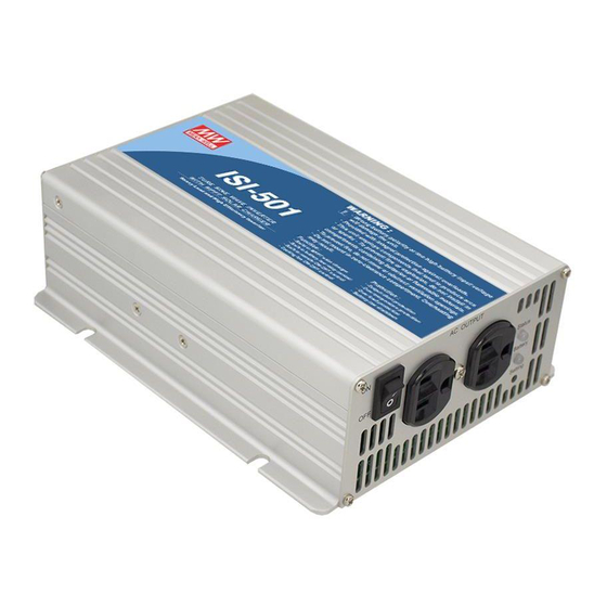
- Page 1 ISI-501 Series Off-Grid Solar Inverter User Manual...
-
Page 2: Table Of Contents
Off-Grid Solar Inverter User Manual Table of Contents 1.Safety Guidelines ................... 2.Introduction .................... Features ................... Main Specification ................................3.User Interface Panel Front Panel ..................LED indicator on Front Panel ............Rear Panel ..................4.Output Voltage and Frequency Settings ..........Initial Factory State ................ -
Page 3: Safety Guidelines
1.Safety Guidelines (Please read through this manual before assembling the Inverter) Risk of electrical shock and energy hazard. All failures should be examined by a qualified technician. Please do not remove the case of the inverter by yourself! Please do not install the inverter in places with high moisture or near water. Please do not install the inverter in places with high ambient temperature, under direct sunlight, or near fire source. -
Page 4: Features
Features 500W rated output Surge power capability up to 1000W True sine wave (THD<3%) ± AC output voltage regulation : 3% High efficiency up to 88% Built in MPPT solar charger, MPPT efficiency: 98%(Typ.) Adjustable output voltage and frequency LED indication for operation and battery capacity Battery low alarm (with electrically isolated dry contact) Remote ON/OFF function Compliance to FCC / CE regulations... -
Page 5: Led Indicator On Front Panel
LED Indicator (Status): Displays the operation status of the ISI-501. LED Indicator (Battery): Displays remaining capacity of battery. Function Setting: Output voltage and frequency can be set through this button. Power ON/OFF Switch: The inverter will turn OFF if the switch is in the OFF position. -
Page 6: Output Voltage And Frequency Settings
Battery Low Alarm: This is an electrically isolated dry contact which can provide the user with an external control signal. Users will be alarmed of a low battery when the two pins are open and the ISI-501 makes a "beep" sound. Battery Status Connector Status Alarm... - Page 7 AC OUTPUT Status Battery Use an insulated plastic Setting stick to press on the "Setting" button Figure 4.1 Adjusting output voltage and frequency Table 4-1 Voltage & Frequency Chart O/P Voltage 100Vac 110Vac 115Vac 120Vac (200Vac) (220Vac) (230Vac) (240Vac) Frequency ●...
-
Page 8: Operating
5.Operation System On Battery Low Shutdown Auto Recovery (SW-ON) Protection AC Output 14.4/28.8/57.6V Battery Voltage 13/26/52V 10.5/21/42V Charger Status Figure 5.1 Operation Sequence t1: When user turns on the ISI-501, battery voltage will be sensed. If battery voltage is greater than 13/26/52V, it means the battery is adequately charged and the charger circuit will remain de-activated to prevent overcharging. -
Page 9: Protection
ISI-501 internal fuse will blow to protect other circuitry. Please contact your nearest distributer or send the inverter back to Mean Well for repair. (C)Battery Low Shutdown Protection: When the battery voltage is lower than 10.5/21/42V, the ISI-501 will shut down to guarantee the lifetime of the battery. - Page 10 o v e r h e a t e d a n d c a u s e d a n g e r. P l e a s e r e f e r t o t a b l e 7 . 1 o r c o n s u l t w i t h o u r distributors or us if you have any questions.
- Page 11 (D)Suggested Mounting The four holes on the sides of the case allow the users to mount and fix the ISI-501 on a flat surface. (It is highly recommended the ISI-501 is placed horizontally. Also, please pay attention to the ventilation.) (E)Example of System Setup Leads should be as short as possible Greater...
-
Page 12: Troubleshooting
9. Warranty Three years of warranty is provided under normal operating conditions. Please do not change components or modify the unit by yourself or attempt to repair the unit by yourself because Mean Well reserves the right to void the warranty.
Need help?
Do you have a question about the ISI-501 Series and is the answer not in the manual?
Questions and answers