
Related Manuals for Mean Well NTN-5K Series


Summary of Contents for Mean Well NTN-5K Series
- Page 1 T N 5 K Series Installation manual AC Bypass Charger Inverter AC Grid AC Load Battery True Sine Wave Inverter High Reliable Inverter...
- Page 2 NTN-5K is a 5000W highly reliable off-grid true sine wave DC-AC power inverter with built-in AC charger and UPS function(AC by-pass). Its key features include: digital design with MCU control, streamlined control circuitry that quickly responds to environmental changes and improves reliability, high quality fan with low acoustic noise, 10KW peak power, adjustable AC output voltage and frequency, -30~+70 ℃...
-
Page 3: Table Of Contents
Contents 1 Safety Guidelines 5.5 Explanation of Operating Logic 2.Introduction 5.6 AC Charger 2.1 Model Encoding 5.7 CMU2E, the GUI Controller 2.2 Features For the NTN-5K 2 3 Specification 5 8 Factory Resetting 2 4 Derating Curve . Mechanical pecification 6 Communication Protocol .1 M Communication... -
Page 4: Safety Guidelines
.Safety Guideline 2.Introduction Model Encoding Risk of electrical shock and energy hazard ll failures should be examined by the qualified technician. Please do not remove the case of the inverter NTN - by yourself. Please refrain from situating the inverter in damp environments or in close DC input voltage (24: 24Vdc, 48: 48Vdc, 380: 380Vdc) proximity to water sources. -
Page 5: 3 Specification
Specification MODEL NTN-5K-224 NTN-5K-248 NTN-5K-2380 SAFETY STANDARDS CB IEC62368-1, CSA C22.2 No. 62368-1 , TUV BS EN/EN62368-1 , AS/NZS 62368.1, EAC TP TC 004 approved RATED POWER(Continuous) 5000W WITHSTAND VOLTAGE DC I/P - AC:3.0KVAC AC - FG:1.5KVAC ℃ OVER RATED POWER(3 Min.) 5750W ISOLATION RESISTANCE DC I/P - AC O/P, DC I/P - FG, AC O/P - FG: 100M ohms / 500VDC / 25 / 70% RH... - Page 6 MODEL NTN-5K-124 NTN-5K-148 SAFETY STANDARDS CB IEC62368-1, TUV BS EN/EN62368-1 approved RATED POWER(Continuous) 4000W WITHSTAND VOLTAGE DC I/P - AC:3.0KVAC AC - FG:1.5KVAC SAFETY & ℃ OVER RATED POWER(3 Min.) 4600W ISOLATION RESISTANCE DC I/P - AC:100M Ohms AC - FG: 500VDC / 25 / 70% RH PEAK POWER(10 Sec.) 5600W 6000W...
-
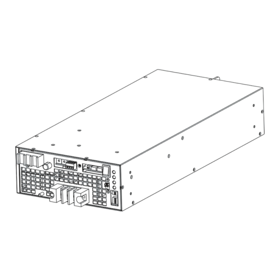
Page 7: 5 . Mechanical Pecification S
erating Curve Mechanical pecification 41.5 4-M4 L=5mm 28 max. AC Output Side 17 max. COMM 83.5 DC Input Side AC INPUT Air flow direction 4-M4 L=5mm (HORIZONTAL) COMM AMBIENT TEMPERATURE ( ) ℃ Air flow AC OUTPUT PAR1 direction PAR2 PAR1 Remote S.W. - Page 8 Accessories ※ NTC Sensor and Remote Control mating along with NTN-5K (Standard accessory) Item Quantity Item Quantity NTC sensor wire UL2468 24x2C 52 mm 40.8 mm NTC(RTH+) NTC(RTH-) NTC mating wire UL1061 24AWG JST PHR 02 or equivalent Connection Diagram Connect to battery Extend cable by customer Connect to...
-
Page 9: Installation & Wiring
3.Installation & Wiring Installation rocedures Turn the inverter off by switching the Main S.W. to the OFF position. 3 1 . Precautions Select appropriate cables for connection between the battery and The unit should be mounted on a flat surface or holding rack the inverter. -
Page 10: User Interface
4.User Interface DC Panel Ventilation slits : AC Panel To ensure proper operation and preserve the lifespan of the inverter, AC bypass input terminals: please ensure suitable ventilation is provided. When AC mains power or utility is available, connecting the input to the AC mains will activate the AC bypass function. -
Page 11: 4 Pin Assignment Of Comm
4.4 Pin Assignment of COMM DC Input Indicator: It is used to show the input status of inverter. Green light When input voltage is greater than 25V 24V 50V 48V 300V 380V Orange light When input voltage is within a range of 22V~25V(24V)/44V~50V(48V) /260V~300V(380V). -
Page 12: Pin Assignment Of Par1,Par2
4.5 Pin Assignment of PAR1,PAR2 4.6 Pin Assignment of R.C. +5V_AUX2 RC_I REMOTE CONTROL GND AUX2 SOLAR_ON_OFF SYNC_BUS SYNC_BUS2 Connector Pin No. Assignment : HRS DF11-08DP-2DS or equivalent Connector Pin No. Assignment : HRS DF11-0 DP-2DS or equivalent Pin No. Function Description Pin No. -
Page 13: Communication Address/Id Assignment
5.Explanation of Operation 4.7 Communication Address/ID Assignment Each NTN-5K unit should have their unique and own device address to communicate Procedure of etting Output voltage, requency over the . AD1 and AD2 allow users to designate an address for the M (with maximum of 64 addresses) . -
Page 14: Parallel Synchronized
Three-phase 4-wire utput Parallel Synchronized Operation (Single-phase Parallel) 5.3.1 NTN-5K has the built-in active current sharing function and can be Three-phase 4-wire Output Setting connected in parallel, up to 6 units, to provide higher output power as Users can connect three units of NTN-5K to form a three-phase 4-wire output, providing three AC voltage sources with equal voltage, the same exhibited below: frequency, but a phase difference of 120°. - Page 15 Arrangement for the AC input ◎ Instructions for connecting units of NTN-5K per phase, connections and settings for PAR1/PRL are as follows: L1 phase L2 phase L3 phase Quantity PSU1 PSU2 PSU3 PSU4 PSU5 PSU6 PAR1 PAR1 PAR1 PAR1 PAR1 PAR1 6 units N1/N2/N3...
-
Page 16: Remote On-Off Control
◎ Instructions for connecting FIVE units of NTN-5K per phase, Pin 1 to pin 2 shorted; Pin 3 to pin 4 shorted connections and settings for PAR1/PRL are as follows: L1 phase L2 phase L3 phase Quantity PSU1 PSU5 PSU6 PSU10 PSU11 PSU15... - Page 17 t1:When the user turns on the NTN-5K and the AC input detects utility 5.5.1 Explanation of UPS Mode power, the inverter automatically enters bypass mode, allowing the utility power to directly feed to the loads and charging the battery Utility power simultaneously.
- Page 18 5.5.2 Explanation of Energy Saving Mode Control Logic t1: When the user turns on the NTN-5K and the AC input detects utility power, the NTN-5K automatically enters bypass mode. Unlike UPS mode, the Load Condition Indicator flashes bypass mode, Utility power making it easier for users to identify the difference.
-
Page 19: Ac Charger
5.5.3 Configuration Recommendation for an External Charger 5.6 1 2 Stage Charging Under UPS Mode Energy-saving Mode , adding an MPPT solar In the initial stage of charging, the charger charges the battery charger at the battery end can extend the battery's usage time. with the maximum current. - Page 20 5.6 2 3 Stage Charging 5.6.3 Setting of Charging Curve In the initial stage of charging, the charger charges the battery The factory default parameters are set to 'Default, with the maximum current. After a period of time (depending on programmable', and they are detailed in the tables below.
- Page 21 The CMU2E is a remote monitoring module designed to be used with product can be connected to the batter y for sensing the NTN-5K series. With its intuitive 7-inch TFT LCD touchscreen temperature of the battery. The charge is able to work panel and physical buttons, users can easily perform on-site normally without the sensor.
-
Page 22: 8 Factory Resetting
6 Communication Protocol Example of u ser nterface 6.1 M Communication Interface The device supports Modbus RTU with the master-salve principle. Users are able to read and write parameters of the device through the protocol, including remote ON/OFF, AC voltage/frequency setting, etc. - Page 23 . .2 M odbus Frame Encapsulation . .5 Data Field and Command Lists us RTU consists of Additional Address, Function Code, Data field provides additional information by the slave to Data and Error Check. complete the action specified by the function code (FC) in a request.
- Page 24 Command list: Function Function # of data # of data Command Command Command Command Description Description code code Bytes Bytes Code Name Code Name Single- hase nput oltage (Bypass) Constant current setting of charge curve 0x0050 READ_VIN 0x04 0x00B1 CURVE_CV 0x03, 0x06 (format: value, F=0.1) (format: value, F=0.01)
- Page 25 Function Function # of data # of data Command Command Command Command Description Description code code Bytes Bytes Code Name Code Name Output AC Voltage Setting Inverter operation status 0x011D INV_STATUS 0x04 110/220series: reading 1: 100/200 Inverter abnormal status 2: 110/220 0x011E INV_FAULT 0x04...
- Page 26 ◎MFR_ID_B0B5(0x0080) is the first 6 codes of the manufacturer's name ◎MFR_REVISION_B0B5 (0x008C) is the firmware revision. A range of 0x00 (ASCII); MFR_ID_B6B11(0x0083) is the last 6 codes of the hexadecimal (R00.0)~0xFE (R25.4) represents the firmware version of manufacturer's name (ASCII) an MCU;...
- Page 27 ◎CURVE_CONFIG( ◎CHG_STATUS 0x00B4 ): (0x00B8) : Bit7 Bit6 Bit5 Bit4 Bit3 Bit2 Bit1 Bit0 Bit7 Bit6 Bit5 Bit4 Bit3 Bit2 Bit1 Bit0 High byte High byte FVTOE CVTOE CCTOE FVTOF CVTOF CCTOF NTCER Low byte STGS CUVS Low byte FULLM Low byte Low byte Bit 0:1 CUVS Charge Curve Selection...
- Page 28 Bit 7 FTTOF: Time Out Flag of Float Mode Bit 4:7 IOUT Factor/IDC Factor: The Factor of output curren t/ DC current 0 NO time out in float mode = 0x0=Output current relevant commands not supported 1 float mode timed out =...
- Page 29 byte2: Bit 4:7 Watt Factor:The Factor of output AC wattage ( Power/Reactive/VA Bit 0:3 TEMPERATURE_1 Factor:The Factor of internal ambient temperature 0x0=AC wattage relevant commands not supported 0x0=internal ambient temperature relevant commands not supported 0x1~0x3= Not in use, reserved (default 0x1~0x3= Not in use, reserved (default 0x4=0.001...
- Page 30 ◎SYSTEM_CONFIG (0x00C4): ◎INV_CONFIG( x0101): Bit7 Bit6 Bit5 Bit4 Bit3 Bit2 Bit1 Bit0 Bit7 Bit6 Bit5 Bit4 Bit3 Bit2 Bit1 Bit0 Low byte INV_PRIO High byte EEP_OFF EEP_CONFIG High Byte Low byte Bit : EEP_CONFIG: EEPROM Configuration Bit 0:1 INV_PRIO: Operation mode selection 00: Immediate.
- Page 31 Bit 5 SAVING: Saving Mode Bit 4 INV_UVP: Inverter UVP 0=The inverter is NOT in Saving M 0= No 1=The inverter is in Saving M 1= Yes Bit 6 : Bat_Low_ALM : Battery low a larm Bit 5 INV_OVP: Inverter OVP 0=...
-
Page 32: 2 Communication Examples
6 2 Communication Examples Response: 0xC0 0x04 0 1 70 The following provides examples of request and response for each function code of the Modbus RTU. 0xC0: Slave ID 0 0x0 : Function code 4 (Read Analog Input Register) 6.2.1 Function code 0x02: The number of data bytes to follow (2 bytes) 6.2.1.1 Read Holding Registers (FC = 03) 0x1 70:... - Page 33 6.2.3 Remote on/off via communication ◎Adding a 120 termination resistor to both the controller and If ON/OFF control of the AC output via communication is inverter end can increase communication stability required, first set Bit 1 (OP_EN) of INV_OPERATION(0x0100) to ◎...
-
Page 34: Value Range And Tolerance
6.3 Value range and tolerance 5.Set constant voltage to 56V (1)Display parameters 0xC0 0x06 0x00B1 0x15E0 0xC624 Display value us Command Model Tolerance 0xC0: Slave ID0 range 0x06: Function code 6 (Write Single Register) 124/148 0~132Vac ±1.1Vac 0x0050 READ_VIN 0x00B : CURVE_C V register 224/248/2380 0~264Vac... - Page 35 Display value Display value us Command Model Tolerance us Command Model Tolerance Default range range 0x0125 READ_BP_VA_HI ±300VA 0x00B9 BAT_ALM_VOLT 2380 275V~335V ±3.8V 300V 0~10000VA 0x0126 READ_BP_VA_LO ±300VA 124/224 19.4V~24V ±0.24V 124/148 0 10 ±1A 0x00BA BAT_SHDN_VOLT 148/248 38.8V~48V ±0.48V 0x012B READ_AC_IOUT 224/248/2380...
-
Page 36: Protections And
If the inverter cannot Load operate normally afterwards, it represents that the inverter is Note: Light damaged. Please return the unit to MEAN WELL's distributor for further service. Flash Light off Inverter Protection: Over Temperature Protection (OTP): When the temperature inside the inverter reaches a certain level, the inverter will automatically turn off for protection. -
Page 37: Warranty
※ MEAN WELL posses the right to adjust the content of this manual. Please refer to the latest version of our manual on our website. https://www.meanwell.com... - Page 38 NTN-5K 5000W DC-AC , ( )。 : 、 、 、 、 10KW 、 、- 30~+ 70℃ 、 。 , NTN-5K 、 、 、 、 、 , 、 、 、 、 、 、 、 、 、 、 、 、 、 。...
Need help?
Do you have a question about the NTN-5K Series and is the answer not in the manual?
Questions and answers