Table of Contents
Advertisement
CRS-3/IR/LSD
CRS-2/IR/LSD
Read this entire installation manual to ensure proper installation, then
file these instructions with the owner or maintenance department.
Flush all the water supply lines before making connections. Debris in
supply lines will cause the valves to malfunction.
Wall anchors used must have a minimum pull-out rating of 1,000 lbs.
Product warranties may be found under "Product Information" on our
web site at www.bradleycorp.com.
215-1330 Rev. K; EN 06-915
© 2007 Bradley Corporation
Page 1 of 14
2/8/07
Table of Contents
Dimensions . . . . . . . . . . . . . . . . . . . . . . . . . . . . . . . .2
Installation Instructions . . . . . . . . . . . . . . . . . . . . . 3-9
Solenoid Valve Troubleshooting . . . . . . . . . . . . . . .11
Solenoid Valve Repair Parts . . . . . . . . . . . . . . . . . .12
Vernatherm™ Valve Troubleshooting . . . . . . . . . . .13
Vernatherm™ Valve Repair Parts . . . . . . . . . . . . . .14
Cleaning the Strainer . . . . . . . . . . . . . . . . . . . . .13-14
For soap system installation, refer to installation manual
215-1583
NOTE: 3-station unit is shown throughout. 2-station
is similar.
IMPORTANT
U P
NAHB
NAHB
C
RESEARCH
RESEARCH
C E N T E R
C E N T E R
C
R
Installation
Instructions
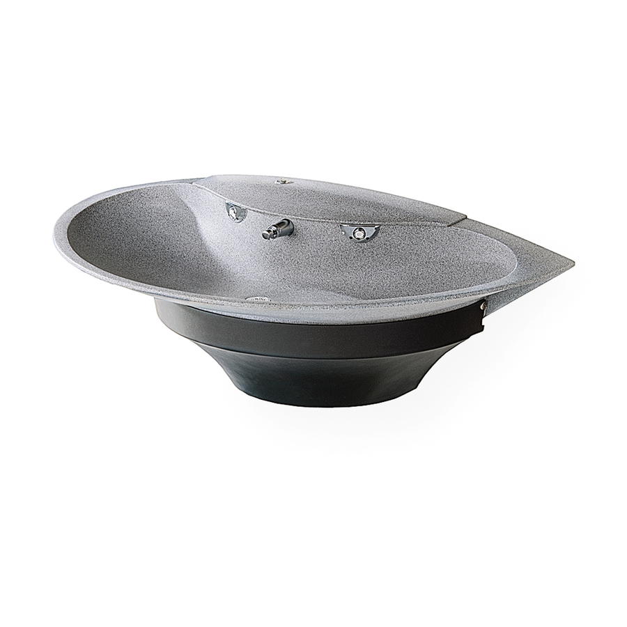
CRS-2/IR, CRS-3/IR
Express® Crescent®
Lavatory System
CRS-Series
Complies with Texas
Accessibility Standards (TAS)
for Juvenile Height applications.
P.O. Box 309, Menomonee Falls, WI 53052-0309
TEL. 1-800-BRADLEY
http://www.bradleycorp.com
TAS
FAX 262-251-5817
Advertisement
Table of Contents
Troubleshooting

Related Manuals for Bradley Express Crescent CRS-2/IR


Summary of Contents for Bradley Express Crescent CRS-2/IR
-
Page 1: Table Of Contents
CRS-3/IR/LSD CRS-2/IR/LSD Read this entire installation manual to ensure proper installation, then file these instructions with the owner or maintenance department. Flush all the water supply lines before making connections. Debris in supply lines will cause the valves to malfunction. Wall anchors used must have a minimum pull-out rating of 1,000 lbs. -
Page 2: Dimensions
® ® Express Crescent Lavatory System - CRS-Series CRS-2/IR, CRS-3/IR Express® Crescent® Lavatory System Dimensions 14" (356) 26" (660) 26" (660) *34" (864) 2/8/07 48" (1219) 48" (1219) 8-1/2" (216) ADJUSTMENTS TO VERTICAL DIMENSIONS Rim Height 34" *37-3/8" (949) 32" 30"... -
Page 3: Installation Instructions
Installation Instructions Installation Instructions Supplies required for installation: • (6) 3/8" wall anchors, bolts and washers to mount bowl to wall (min. pull-out force of 1,000 lbs.) • 1/2" NPT hot and cold or tempered supply piping • 1-1/2" drain piping and P-Trap (available from Bradley, p/n 269-1697) •... - Page 4 ® ® Express Crescent Lavatory System - CRS-Series CRS-2/IR, CRS-3/IR Installation Instructions continued . . . Step 1: Rough-ins cont’d. 2. Install a 110 volt GFI protected electrical outlet per local code at the location shown in Figure 2. 3. Install six 3/8" wall anchors with a minimum pull-out rating of 1,000 lbs. (supplied by installer) at the locations marked in Figure 2.
- Page 5 Installation Instructions Installation Instructions continued . . . Step 3: Install wall anchors 1. Measure and mark the centerline of the lavatory system on the wall. 3. Using cardboard template 186-1311 provided, mark six mounting holes on wall. 3. Drill holes in the wall and install the six 3/8" wall anchors with a minimum pull-out rating of 1,000 lbs.
-
Page 6: Drain Assembly
® ® Express Crescent Lavatory System - CRS-Series CRS-2/IR, CRS-3/IR Installation Instructions continued . . . Step 6: Install drain spud 1. Assemble the P-trap by (supplied by installer) connecting the 1-1/2" tubular pipe to the 1-1/4" tailpiece and to the 1-1/2" drain pipe stubbed out of the wall (see Figure 4). - Page 7 Installation Instructions Installation Instructions continued . . . Electrical and supply connections Step 8: NOTE: Refer to Figure 6a below for CRS-2/IR or Figure 6b on page 8 for CRS-3/IR. WARNING: The Adaptive® Infrared control must be connected with a 24 VAC Class II transformer.
- Page 8 ® ® Express Crescent Lavatory System - CRS-Series CRS-2/IR, CRS-3/IR Installation Instructions continued . . . BLACK SUPPLY TUBE (FROM SPRAYHEAD) SENSOR CIRCUIT PLUG TRANSFORMER CIRCUIT PLUG SUPPLY INLET VERNATHERM™ THERMOSTATIC MIXING VALVE Figure 6b Installation Instructions continued . . . Electrical and supply connections, cont’d.
- Page 9 Installation Instructions Installation Instructions continued . . . Step 9: Install the Optional Soap Dispenser For Express® Crescent® Lavatory System units with optional soap dispensers, see 215-1583. Step 10: Install the top cover 1. Carefully place the top cover on top of the lavatory system bowl. 2.
-
Page 10: Cleaning And Maintenance Instructions
® ® Express Crescent Lavatory System - CRS-Series CRS-2/IR, CRS-3/IR Cleaning and Maintenance Instructions IMPORTANT: Strong alkaline or acid-based chemicals and cleansers should not be used to clean the Crescent®. If these chemicals come in contact with the Terreon® surface, wipe off the surface immediately and flush with soapy water. -
Page 11: Solenoid Valve Troubleshooting
Installation Instructions Solenoid Valve Troubleshooting CAUTION: Turn off water supplies to unit before troubleshooting. Problem: An individual operating station fails to shut off and drips. Cause: There is debris trapped between the diaphragm and the valve seat. Solution: Remove debris between diaphragm and the valve seat. 1. -
Page 12: Solenoid Valve Repair Parts
® ® Express Crescent Lavatory System - CRS-Series CRS-2/IR, CRS-3/IR Solenoid Valve S07-067 (closed body) and S07-067A (thru body) Figure 8 2/8/07 REF. QTY. PART NO. 118-307 118-307A 269-983 269-577 269-578 269-1729 269-1730 269-579 160-447 125-165 Bradley Corporation • 215-1330 Rev. K; EN 06-915 Installation Instructions DESCRIPTION VALVE BODY, 1/4"... -
Page 13: Thermostatic Mixing Valve Troubleshooting
Installation Instructions Thermostatic Mixing Valve Troubleshooting NOTE: Before attempting to troubleshoot the valve or disassemble the components, check for the following conditions: • If stop/check valves are used, make sure that they are fully open. • Make sure that the hot and cold inlet pipes are connected properly, and that there are no cross- connections or leaking stop/check valves. -
Page 14: Vernatherm™ Valve Repair Parts
® ® Express Crescent Lavatory System - CRS-Series CRS-2/IR, CRS-3/IR Vernatherm™ Thermostatic Mixing Valve (S01-524) Repair Kit S65-259 Item Description Thermostat O-Ring O-Ring Strainer (173-028) Figure 9 Tempered Line Adapter Assembly (S39-685) Option Figure 10 Strainer 173-028 2/8/07 Bradley Corporation • 215-1330 Rev. K; EN 06-915 Installation Instructions Nut 3/8-24 Hex Jam O-Ring...
Need help?
Do you have a question about the Express Crescent CRS-2/IR and is the answer not in the manual?
Questions and answers