Siemens SITRANS F M MAG 5100 W Operating Instructions Manual
Hide thumbs
Also See for SITRANS F M MAG 5100 W:
- Operating instructions manual (66 pages) ,
- Instructions manual (32 pages) ,
- Handbook (92 pages)
Table of Contents
Advertisement
Advertisement
Table of Contents

Related Manuals for Siemens SITRANS F M MAG 5100 W


Summary of Contents for Siemens SITRANS F M MAG 5100 W
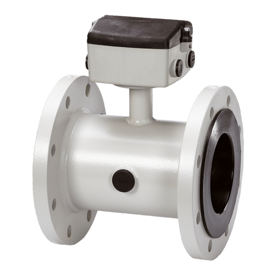
- Page 1 SITRANS FM MAG 5100 W Manual...
- Page 2 For drinking water applications, EPDM liners are used. They may work with pressure up to 40 bar. Siemens MAGFLO 5100W has a special robust design and func tions for working with electrically conductive fluids. It is suit able for working with any type of water.
- Page 3 Introduction Safety notes Description SITRANS F Installing/Mounting Electromagnetic Flowmeters SITRANS F M MAG 5100 W Connecting Service and maintenance Operating Instructions Troubleshooting/FAQs Technical data Appendix info@eltra-trade.com +421 552 601 099 www.eltra-trade.com...
- Page 4 Note the following: WARNING Siemens products may only be used for the applications described in the catalog and in the relevant technical documentation. If products and components from other manufacturers are used, these must be recommended or approved by Siemens. Proper transport, storage, installation, assembly, commissioning, operation and maintenance are required to ensure that the products operate safely and without any problems.
-
Page 5: Table Of Contents
Table of contents Introduction..............................5 Items supplied ..........................5 History ............................5 Further Information ........................6 Safety notes............................... 7 Laws and directives ........................7 Installation in hazardous area ......................9 Certificates ...........................10 Description............................... 11 System components ........................11 Theory of operation........................12 Installing/Mounting........................... 15 Installation safety precautions......................15 Determining a location .........................16 Orienting the sensor........................18 Mounting ............................19... - Page 6 Table of contents Technical data ............................37 MAG 5100 W..........................37 Cable data ........................... 40 Effect of temperature on working pressure ................. 41 Process fluid conductivity......................42 Liner selection ..........................43 Electrode selection........................43 Sizing tables..........................44 Dimensions and weight ....................... 46 Appendix..............................
-
Page 7: Introduction
It is the responsibility of the customer that the instructions and directions provided in the manual are read, understood and followed by the relevant personnel before installing the device. Items supplied SITRANS F M MAG 5100 W Calibration report SITRANS F M literature CD Quick Start guide... -
Page 8: Further Information
Product information on the Internet The Operating Instructions are available on the CD-ROM shipped with the device, and on the Internet on the Siemens homepage, where further information on the range of SITRANS F flowmeters may also be found: Product information on the internet (http://www.siemens.com/flowdocumentation) -
Page 9: Safety Notes
Material compatibility Siemens Flow Instruments can provide assistance with the selection of wetted sensor parts. However, the full responsibility for the selection rests with the customer and Siemens Flow Instruments can take no responsibility for any failure due to material incompatibility. - Page 10 "Pressure Equipment Directive" (PED) is mandatory for all pressure equipment sold within the EU and EFTA. Siemens Flow Instruments products confirms to PED by following the tables below. Table 2- 1 MAG 5100 W (7ME6580 only DN15 ... 600 (½" ... 24"))
-
Page 11: Installation In Hazardous Area
Safety notes 2.2 Installation in hazardous area PED* PED* 1000 PED* 1050 1100 1200 PED* The key to the tables is as follows: Product covered by PED and only available as fully PED-conforming PED* Product covered by PED but available as either conforming or non-conforming to Excluded from PED under Sound Engineering Practice Excluded from PED under the Low Voltage Directive Installation in hazardous area... -
Page 12: Certificates
Connect the devices that are operated in hazardous areas as per the stipulations applicable in the country of operation. Certificates Certificates are posted on the Internet and on the documentation CD-ROM shipped with the device. See also Technical data (Page 37) Certificates on the Internet (http://www.siemens.com/processinstrumentation/certificates) info@eltra-trade.com +421 552 601 099 www.eltra-trade.com... -
Page 13: Description
Description The main applications of the SITRANS F M electromagnetic flow sensors can be found in the following fields: ● Process industry ● Chemical industry ● Steel industry ● Mining ● Utility ● Power generation & distribution ● Oil & gas / HPI ●... -
Page 14: Theory Of Operation
Description 3.2 Theory of operation The SITRANS F M MAG 5100 W sensor housing and flanges are designed in carbon steel and terminal box in fibre glass reinforced polyamide. Measuring pipe is made of stainless steel (AISI 304) and liners are available in NBR Hard Rubber, Ebonite Hard Rubber, or EPDM, which makes the sensor highly resistant to a wide range of chemicals. - Page 15 Description 3.2 Theory of operation = When an electrical conductor of length L is moved at velocity v, perpendicular to the lines of flux through a magnetic field of strength B, the voltage Ui is induced at the ends of the conductor = L x B x v ●...
- Page 16 Description 3.2 Theory of operation info@eltra-trade.com +421 552 601 099 www.eltra-trade.com...
-
Page 17: Installing/Mounting
Installing/Mounting SITRANS F flowmeters with minimum IP67/NEMA 4X enclosure rating are suitable for in- and outdoor installations. ● Make sure that pressure and temperature specifications indicated on the device nameplate / label will not be exceeded. WARNING Installation in hazardous location Special requirements apply to the location and interconnection of sensor and transmitter. -
Page 18: Determining A Location
Installing/Mounting 4.2 Determining a location Determining a location NOTICE The sensor must always be completely filled with liquid. ● Locate the the flowmeter in u-shaped pipes if pipes are only partially filled or have free outlet Figure 4-1 Correct installation in U-tube ●... - Page 19 Installing/Mounting 4.2 Determining a location Figure 4-4 Inlet and outlet conditions Installation in large pipes The flowmeter can be installed between two reducers (e.g. DIN 28545). At 8° the following pressure drop curves apply. The curves are applicable to water. Example: A flow of 3 m/s (V) in a sensor with a diameter reduction from DN 100 to DN 80 (d = 0.8)
-
Page 20: Orienting The Sensor
Installing/Mounting 4.3 Orienting the sensor Orienting the sensor The sensor operates in all orientations, but Siemens has the following recommendations: ● Vertical installation with an upwards flow Figure 4-5 Vertical orientation, upwards flow CAUTION Abrasive liquids / liquids containing solid particles... -
Page 21: Mounting
● Use proper gaskets according to liner type Figure 4-7 Correct installation with gaskets Vibrations Avoid strong vibrations. Figure 4-8 Avoid vibrations CAUTION In applications with strong vibrations, Siemens recommend remote mounting of the transmitter! info@eltra-trade.com +421 552 601 099 www.eltra-trade.com... - Page 22 Installing/Mounting 4.4 Mounting Torques Fasten screws according to the torques values below Figure 4-9 Torques values NOTICE Torque values are calculated on the basis of use of gaskets. Table 4- 1 Maximum allowable torques PN 10 PN 16 PN 40 Class 150 AWWA Inch...
-
Page 23: Potential Equalization
Installing/Mounting 4.5 Potential equalization PN 10 PN 16 PN 40 Class 150 AWWA 32" 274/274 202/202 386/380 285/285 36" 288/288 213/213 408/408 301/301 1000 40" 382/382 282/282 546/546 403/403 1050 42" 1100 44" 1200 48" 395/395 292/292 731/731 539/538 1400 54"... - Page 24 Installing/Mounting 4.5 Potential equalization Figure 4-11 Cathodic protection ● Isolate the sensor from cathodic protected pipes using insulated bolts. ● Use bypass cable between the mating flanges NOTICE Remote mounted sensor versions If the above is not acceptable, remote mounted sensors can alternatively be connected as follows: ...
-
Page 25: Connecting
Connecting The following contains a short description of how to connect a remote mounted sensor to a transmitter type SITRANS F M MAG 5000 / 6000 or MAG 6000 I. For more information, e.g. about wiring of power supply and outputs, refer to the Operating Instructions for the respective transmitters. -
Page 26: Remote Installation
Connecting 5.1 Remote installation ● To guarantee the IP 67 degree of protection, use cables with the required specifications. WARNING Protective conductor terminal The required cable is min. AGW16 or 1.5 Cu. WARNING Wire insulation The insulation between the connected mains supply and 24 V AC/DC supply for the flowmeter must at least be rated with double or reinforced insulation at mains voltage. - Page 27 Connecting 5.1 Remote installation 2. Remove SENSORPROM unit from sensor and mount it on connection plate in ® transmitter, see relevant transmitter operating instructions. 3. Fit the ½" NPT or M20 cable glands for supply and output cables. 4. Fit and connect electrode and coil cables as shown below. CAUTION Unshielded cable ends Keep unscreened cable ends as short as possible.
-
Page 28: Installation Check
Connecting 5.2 Installation check 5. Tighten cable glands well to obtain optimum sealing. WARNING Mount terminal box lid before power up. Installation check The meter is now ready to go into normal operation - for commissioning and setting of parameters refer to the relevant transmitter manual. Before commissioning it must be checked that: ●... - Page 29 Connecting 5.3 Potting Horizontal orientation Vertical orientation NOTICE Gel can be penetrated with test instruments or be removed in case of cable replacement. info@eltra-trade.com +421 552 601 099 www.eltra-trade.com...
-
Page 30: Direct Burial
Connecting 5.4 Direct burial Direct burial Recommendations for direct burial of remote sensor: ● Check for visible damages in paint finish ! ● Use protection conduit ! ● Protect sensor with pea gravel at least 3000 mm around sensor. This provides some drainage and also avoids caking sensor with earth. -
Page 31: Service And Maintenance
● Seal integrity of the process connections, cable entries, and cover screws ● Reliability of power supply, lightning protection, and grounds Recalibration Siemens A/S Flow Instruments offers to recalibrate the sensor. The following calibrations are offered as standard: ● Standard matched pair calibration... -
Page 32: Unit Repair
Figure 6-1 Handling of sensor Unit repair CAUTION Repair and service must be carried out by Siemens authorized personnel only. Note Siemens Flow Instruments defines sensors as non-repairable products. Technical support If you have any technical questions about the device described in these Operating Instructions and do not find the right answers, you can contact Technical Support: ●... -
Page 33: Return Procedures
● Information about field service, repairs, spare parts and lots more under "Services." Additional Support Please contact your local Siemens representative and offices if you have additional questions about the device Find your contact partner at: Local contact person (http://www.automation.siemens.com/partner) - Page 34 Service and maintenance 6.6 Return procedures ● Declaration of Decontamination Declaration of Decontamination (http://pia.khe.siemens.com/efiles/feldg/files/Service/declaration_of_decontamination_en. pdf) that the returned products/spare parts have been With this declaration you certify carefully cleaned and are free from any residues. If the device has been operated together with toxic, caustic, flammable or water- damaging products, clean the device before return by rinsing or neutralizing.
-
Page 35: Troubleshooting/Faqs
Troubleshooting/FAQs Sensor check Requirement To check the SITRANS F M sensors the following test instruments will be required: ● Digital Meter/Multimeter ● Megger ● (Moving Coil Meter) Sensor check Remove the transmitter from the sensor or remote position before making the following checks. - Page 36 Troubleshooting/FAQs 7.1 Sensor check Sensors with an insulation resistance down to 1 Megohms may still work satisfactorily but this is not guaranteed. Electrode resistance check ● Measure the electrode resistance between connections 82 and Zero with a moving coil meter. With a sensor full of fluid the resistance should be between 5Kohms and 50Kohms.
-
Page 37: Fluctuating Process Values
Troubleshooting/FAQs 7.2 Fluctuating process values Fluctuating process values Question Why do the displayed process values fluctuate when the electrode cable is moved? Answer There are several causes to the fluctuating process values: ● Deposits on electrodes – Clean the electrodes. ●... - Page 38 Troubleshooting/FAQs 7.2 Fluctuating process values info@eltra-trade.com +421 552 601 099 www.eltra-trade.com...
-
Page 39: Technical Data
Technical data MAG 5100 W Table 8- 1 Technical data Version MAG 5100W (7ME6520) MAG 5100W (7ME6580) Product characteristic Mainly for the European market Mainly for the non-European market EPDM or NBR lining Ebonite lining Coned sensor: Full bore sensor: Design and nominal size DN 15 ... - Page 40 Technical data 8.1 MAG 5100 W Version MAG 5100W (7ME6520) MAG 5100W (7ME6580) AWWA C-207 Class D: Class D: 28" ... 48", Flat face flanges 28" ... 78", Flat face flanges PN 16 (230 psi): PN 16 (230 psi): AS4087 DN 50 ...
- Page 41 Technical data 8.1 MAG 5100 W Version MAG 5100W (7ME6520) MAG 5100W (7ME6580) Process fluid temperature -10 ... +70 °C (14 ... 158 °F) EPDM -10 ... +70 °C (14 ... 158 °F) EPDM (MI-001) +0.1 ... +30 °C (32 ... 76 °C) Ebonite -10 ...
-
Page 42: Cable Data
Technical data 8.2 Cable data Version MAG 5100W (7ME6520) MAG 5100W (7ME6580) EPDM liner: Drinking water approvals ANSI/NSF 61 Standard (Cold water, NSF/ANSI Standard 61 (Cold water, WRAS (WRc, BS6920 cold water, WRAS (WRc, BS6920 cold water, ... -
Page 43: Effect Of Temperature On Working Pressure
Technical data 8.3 Effect of temperature on working pressure Coil cable Standard electrode cable Max. cable loop resistance Media temperature: < 100 °C 40 Ω > 200 °C 6 Ω Cable glands on sensor M20x1.5 gland - Cable ø 5 ... 13 mm (0.20 ... 0.51 inches) and transmitter ½... -
Page 44: Process Fluid Conductivity
Technical data 8.4 Process fluid conductivity Flange Flange rating Temperature (°C) specifications Sizes DN 15 ... 300 (order no. 7ME6520 only) EN 1092-1 PN 10 10.0 10.0 10.0 PN 16 10.0 16.0 16.0 13.2 PN 40 40.0 40.0 38.7 37.7 ANSI B16.5 150 lb 10.0... -
Page 45: Liner Selection
Technical data 8.5 Liner selection Special cable [µS/cm] Conductivity of medium 150 300 600 1200 1500 [ft] Cable length WARNING For detection of empty sensor the min. conductivity must always be >50 μS/cm and the max. length of the electrode cable when remote mounted is 50 meters (164 ft). Special cable must be used! For remote MID installations the max. -
Page 46: Sizing Tables
Technical data 8.7 Sizing tables Sizing tables Sizing table (DN 2 ... DN 2000) info@eltra-trade.com +421 552 601 099 www.eltra-trade.com... - Page 47 Technical data 8.7 Sizing tables Sizing table (DN " ... DN 78") The tables show the relationship between flow velocity v, flow quantity Q and sensor dimension DN. Guidelines for selection of sensor Min. measuring range: 0 ... 0.25 m/s (0 ... 0.8 ft/s) Max.
-
Page 48: Dimensions And Weight
Technical data 8.8 Dimensions and weight Flow velocity calculation formula: (metric measures) 1273.24 x Q [l/s] 353.68 x Q [m [m/s] or V = [m/s] [mm] [mm] (imperial measures) 0.408 x Q [GPM] 283.67 x Q [MGD] [ft/s] or V = [ft/s] (Pipe ID) [inch]... - Page 49 Technical data 8.8 Dimensions and weight Dimensions Table 8- 10 Nominal size A Nominal size Order no. Order no. 7ME6520 NBR or EPDM liner 7ME6580 Ebonite liner inch inch inch ½ 1½ 2½ 10.0 10.9 10.1 12.0 11.2 13.1 12.2 14.1 15.0 14.3...
- Page 50 Technical data 8.8 Dimensions and weight Table 8- 11 Nominal size L Nominal size PN 10 PN 16 PN 16 PN 40 Class 150 AS / JIS10K non-PED AWWA inch inch inch inch inch inch inch ½ 1½ 2½ 11.8 11.8 11.8 13.8...
- Page 51 Technical data 8.8 Dimensions and weight Weight Table 8- 12 Weight Nominal size Order no. Order no. 7ME6520 7ME6580 PN 10 PN 16 PN 40 Class 150 / PN / ANSI / AWWA AWWA / AS inch ½ 1½ 2½ 10.7 11.6 15.2...
- Page 52 Technical data 8.8 Dimensions and weight info@eltra-trade.com +421 552 601 099 www.eltra-trade.com...
-
Page 53: Appendix
Appendix Flange mating dimensions (metric) Figure A-1 Flange mating dimensions Table A- 1 Flange mating dimensions (metric) Dimensions (mm) Bolting Holes Bolts PN10 1015 1115 1050 1000 1230 1160 1200 1455 1380 PN16 info@eltra-trade.com +421 552 601 099 www.eltra-trade.com... - Page 54 Appendix A.1 Flange mating dimensions (metric) Dimensions (mm) Bolting Holes Bolts 1025 1125 1050 1000 1255 1170 1200 1485 1390 PN40 150 lb 36.5 info@eltra-trade.com +421 552 601 099 www.eltra-trade.com...
-
Page 55: Factory Settings
Appendix A.2 Factory settings Dimensions (mm) Bolting Holes Bolts AWWA 1060 1168 1068 1000 1289 1200 1050 1346 1257 1200 1511 1422 Factory settings Dimension-dependent factory settings Table A- 2 50 Hz version Qmax Unit Volume/ Pulse Totalizer unit unit pulse Order no. - Page 56 Appendix A.2 Factory settings Qmax Unit Volume/ Pulse Totalizer unit unit pulse Order no. 7ME6520 Order no. 7ME6580 9000 572.5 22902 572.5 22902 1000 12000 706.8 28274 706.8 28274 1050 12000 706.8 28274 706.8 28274 1100 14000 855.2 34211 855.2 34211 1200 15000...
-
Page 57: Coil Resistance
Appendix A.3 Coil resistance Qmax Unit Volume/ Pulse Totalizer unit unit pulse Order no. 7ME6520 Order no. 7ME6580 1200 66043 4481 179262.9 4481 179262.9 US GPM 10 US G US MG 1400 110072 6099.9 243993.7 US GPM 1000 US G US MG 1500 132086... - Page 58 Appendix A.3 Coil resistance MAG 1100, MAG 1100F MAG 3100, MAG 3100P, MAG 5100 W MAG 5100 W (Order no. 7ME6580) (Order no. 7ME6520) 1000 +/− 4 +/− 6 1100 1200 +/− 4 +/− 6 1400 1500 1600 1800 2000 On MAG 1100 DN 15 produced as from May 1999 the coil resistance must be 86 ohm, +8/−4 ohm.
-
Page 59: Ordering
P68/NEMA 6P (not for EX) Ordering In order to ensure that the ordering data you are using is not outdated, the latest ordering data is always available on the Internet: Catalog process instrumentation (http://www.siemens.com/processinstrumentation/catalogs) info@eltra-trade.com +421 552 601 099 www.eltra-trade.com... - Page 60 Appendix A.4 Ordering info@eltra-trade.com +421 552 601 099 www.eltra-trade.com...
-
Page 61: Glossary
USM II is a Communication Platform. The Siemens USM II concept enables fitting of add-on bus modules without loss of functionality: 1. All modules can be fitted as true "plug & play"... - Page 62 Glossary info@eltra-trade.com +421 552 601 099 www.eltra-trade.com...
-
Page 63: Index
Index Abrasive liquids, 18 Hazardous area Add-on modules, (See Communication module) Approvals, 10 Applications, 11 Horizontal pipes Installation in, 18 Hotline, 30 Cable specifications, 24, 40 Cathodic protection, 21 Coil insulation check, 33 Inlet / outlet conditions, 16 Coil resistance check, 33 Installation Communication modules, 11 in U-tube, 16... - Page 64 Index Pressure Equipment Directive, 8 Process fluid Conductivity, 42 Protective conductor terminal, 24 Protective earth, 24 Recalibration, 29 Repair, 30 Return procedures, 31 Safety Instrument safety standards, 7 Safety instructions Electrical connection, 23 Installation, 15 Safety notes, 7 Sensor check, 33 Sensor orientation, 18 Service, 30, 31 Support, 31...
- Page 65 We supply: SITRANS FM Magflo Eltra Trade s.r.o. supplies full range of SIEMENS SITRANS F SIEMENS MAG 1100 products with the best prices SIEMENS MAG 3100 and delivery terms. SIEMENS MAG 5100 Ø SIEMENS MAG 8000 ...
Need help?
Do you have a question about the SITRANS F M MAG 5100 W and is the answer not in the manual?
Questions and answers