Sign In
Upload
Manuals
Brands
LS Industrial Systems Manuals
Controller
GLOFA G7M-DRT40U(N)
LS Industrial Systems GLOFA G7M-DRT40U(N) Manuals
Manuals and User Guides for LS Industrial Systems GLOFA G7M-DRT40U(N). We have
1
LS Industrial Systems GLOFA G7M-DRT40U(N) manual available for free PDF download: User Manual
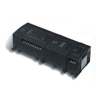
LS Industrial Systems GLOFA G7M-DRT40U(N) User Manual (367 pages)
Programmable Logic Controller
Brand:
LS Industrial Systems
| Category:
Controller
| Size: 15 MB
Table of Contents
Table of Contents
7
Chapter 1 . General
13
Guide to Use this Manual
13
Feature
14
Terminology
16
Chapter 2. System Configuration
19
Overall Configuration
19
Basic System
19
Cnet I/F System
20
Product List
22
Product Functional Block
22
GM7U Series System Equipment Product
23
Chapter 3. General Specifications
25
General Specifications
25
Chapter 4. Names of Parts
26
Main Units
26
Expansion Modules
39
Points I/O Expansion Module
40
Special Modules
42
A/D·D/A Combination Module
42
D/A Conversion Module
43
A/D Conversion Module
44
Analog Timer Module
45
RTD Input Module
45
Communication I/F Module
46
Cnet I/F Module
46
Fnet I/F Module
46
Pnet I/F Module
47
Devicenet I/F Module
47
Rnet I/F Module
47
Chapter 5. Power Supply / CPU
48
Power Supply Specifications
48
AC Power Supply
48
DC Power Supply
48
CPU Specifications
49
Operation Processing
52
Operation Method
52
Operation Processing at Momentary Power Failure
53
Scan Time
54
Scan Watchdog Timer
54
Timer Processing
55
Counter Processing
56
Program
59
1Program Configuration
59
Program Execution Procedure
59
Error Handling
69
Operation Modes
70
RUN Mode
70
STOP Mode
71
PAUSE Mode
71
DEBUG Mode
71
Operation Mode Change
72
Functions
74
Restart Mode
74
Self-Diagnosis
76
Remote Function
76
I/O Force On/Off Function
77
Direct I/O Operation Function
78
External Device Error Diagnosis Function
78
Memory Configuration
80
Structure
82
Usage
83
External Memory Module
84
Structure
84
Usage
84
RTC Option Module
86
Specifications
86
Structure
87
Usage
87
Read RTC Data
88
Write RTC Data
89
Chapter 6. Input and Output Specifications
91
Input / Output Specifications
91
Digital Input Specifications
92
Main Unit
92
Expansion Module
96
Digital Output Specifications
97
Main Unit (Relay Output)
97
Main Unit (NPN TR Output)
100
Main Unit (PNP TR Output)
103
Expansion Module (Relay Output)
106
Expansion Module (TR Output)
107
Chapter 7 . Usage of Various Functions
108
Built-In Functions
108
High Speed Counter Function
108
Pulse Catch
123
Input Filter
124
PID Control
126
Special Modules
149
A/D·D/A Combination Module
150
A/D Conversion Module
161
D/A Conversion Module
168
RTD Input Module
177
Positioning Function
184
Specification
184
Positioning Function
187
Positioning Parameter and Operation Data
200
Instructions
207
Flag List and Error Codes
217
Wiring with Servo and Stepping Motor Drive
221
Chapter 8. Communication Functions
227
Dedicated Protocol Communication
227
Introduction
227
System Configuration Method
228
Frame Structure
231
Commands List
233
Data Type
234
Command Command
237
1:1, 1:N Built-In Communication between LSIS Products
251
Error Codes
263
LS Inverter-Dedicated Protocol
264
User Defined Protocol Communication
267
Introduction
267
Parameter Setting
267
Function Block
275
Example
276
Modbus Protocol Communication
288
Introduction
288
Basic Specifications
288
Parameter Setting
292
Function Block
294
Example
305
No Protocol Communication
309
Introduction
309
Parameter Setting
310
Function Block
311
Examples
313
Remote Connection and Communication I/F Module
315
Remote Connection
315
Communication I/F Module
319
Chapter 9. Installation and Wiring
324
Installation
324
Installation Environment
324
Handling Instructions
326
Connection of Expansion Module
329
Wiring
330
Power Supply Wiring
330
Input and Output Devices Wiring
331
Grounding
332
Cable Specifications for Wiring
332
Chapter 10 . Maintenance
333
Maintenance and Inspection
333
Daily Inspection
333
Periodic Inspection
334
Chapter 11. Troubleshooting
335
Basic Procedure of Troubleshooting
335
Troubleshooting
335
Flowchart for When the "POWER" LED Turned off
336
Flowchart for When the "ERRORR" LED Is Flashing
337
Flowchart for When the "RUN" LED Turned off
338
Flowchart for When the I/O Devices Does Not Operate Normally
339
Flowchart for When Unable to Write a Program to the CPU
341
Troubleshooting Questionnaire
342
Troubleshooting Examples
343
Input Circuit Troubles and Corrective Actions
343
Output Circuit Troubles and Corrective Actions
344
Error Code List
346
Advertisement
Advertisement
Related Products
LS Industrial Systems GLOFA G7M-DRT20U(N)
LS Industrial Systems GLOFA G7M-DRT20U(N)/DC
LS Industrial Systems GLOFA G7M-DRT30U(N)
LS Industrial Systems GLOFA G7M-DRT30U(N)/DC
LS Industrial Systems GLOFA G7M-DRT40U(N)/DC
LS Industrial Systems GLOFA G7M-DRT60U(N)
LS Industrial Systems GLOFA G7M-DRT60U(N)/DC
LS Industrial Systems GLOFA G7M-DR20U/DC
LS Industrial Systems GLOFA G7M-DR30U
LS Industrial Systems GLOFA G7M-DR40U/DC
LS Industrial Systems Categories
Controller
Inverter
Control Unit
DC Drives
Circuit breakers
More LS Industrial Systems Manuals
Login
Sign In
OR
Sign in with Facebook
Sign in with Google
Upload manual
Upload from disk
Upload from URL