Advertisement
Quick Links
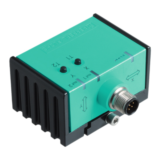
Abmessungen
M12
37
10
4 x ø 5.5
Alle Abmessungen in mm
Elektrischer Anschluss/Kurven/Zusätzliche Informationen
Normsymbol/Anschluss:
1
+U
B
2
Out 2 (Y)
I
4
Out 1 (X)
6
Analogausgang Y
7
Analogausgang X
5
GND
3
-U
B
8
n.c.
1
8
7
2
6
3
5
4
Adernfarben
1
WH
(weiß)
2
BN
(braun)
3
GN
(grün)
4
YE
(gelb)
5
GY
(grau)
6
PK
(pink)
7
BU
(blau)
8
RD
(rot)
Technische Daten
Allgemeine Daten
Typ
Neigungssensor, 2-achsig
Messbereich
0 ... 360 °
Absolute Genauigkeit
≤ ± 0,5 °
Ansprechverzug
≤ 25 ms
Auflösung
≤ 0,1 °
Reproduzierbarkeit
≤ ± 0,1 °
Temperatureinfluss
≤ 0,027 °/K
Kenndaten funktionale Sicherheit
MTTF
300 a
d
Gebrauchsdauer (T
)
20 a
M
Diagnosedeckungsgrad (DC)
0 %
Anzeigen/Bedienelemente
Betriebsanzeige
LED, grün
Teach-In-Anzeige
2 LEDs gelb (Schaltzustand), blinkend
Taster
2 Taster ( Einlernen der Schaltpunkte , Einlernen des Auswertebereiches )
Schaltzustand
2 LEDs gelb: Schaltzustand (je Ausgang)
Elektrische Daten
Betriebsspannung
U
10 ... 30 V DC
B
Leerlaufstrom
I
≤ 25 mA
0
Bereitschaftsverzug
t
≤ 200 ms
v
Schaltausgang
Ausgangstyp
2 Schaltausgänge pnp, Schließer , verpolgeschützt , kurzschlussfest
Betriebsstrom
I
≤ 100 mA
L
Spannungsfall
≤ 3 V
Analogausgang
Ausgangstyp
2 Stromausgänge 4 ... 20 mA
(1 Ausgang für jede Achse)
Lastwiderstand
0 ... 200 Ω bei U
0 ... 500 Ω bei U
Umgebungsbedingungen
Umgebungstemperatur
-40 ... 85 °C (-40 ... 185 °F)
Lagertemperatur
-40 ... 85 °C (-40 ... 185 °F)
Mechanische Daten
Anschlussart
Gerätestecker M12 x 1, 8-polig
Gehäusematerial
PA
Schutzart
IP68 / IP69K
Masse
240 g
Werkseinstellungen
Analogausgang (X)
-45 ° ... 45 °
Analogausgang (Y)
-45 ° ... 45 °
Schaltausgang (X)
-30 ° ... 30 °
Schaltausgang (Y)
-30 ° ... 30 °
Normen- und Richtlinienkonformität
Normenkonformität
Schock- und Stoßfestigkeit
100 g gemäß DIN EN 60068-2-27
Normen
EN 60947-5-2:2007
IEC 60947-5-2:2007
Zulassungen und Zertifikate
UL-Zulassung
cULus Listed, Class 2 Power Source
CSA-Zulassung
cCSAus Listed, General Purpose, Class 2 Power Source
E1-Typgenehmigung
10R-04
Einbaulage
Im Auslieferungszustand ist die Null-Lage der Sensorachsen erreicht, wenn der elektrische Anschluss des Sensors senkrecht nach oben weist.
X-Orientierung
-
+
X = 0°
X = 90°
Dimensions
LEDs
Taster
64
45
10
65
All dimensions im mm
= 10 ... 18 V
B
= 18 ... 30 V
B
X = ±180°
X = 270° (-90°)
M12
LEDs
Button
37
64
10
45
10
4 x ø 5.5
65
Electrical Connection / Curves / Additional Information
Standard symbol/Connection:
1
+U
B
2
Out 2 (Y)
I
4
Out 1 (X)
6
Analogue output Y
7
Analogue output X
5
GND
3
-U
B
8
n.c.
1
8
7
2
6
3
5
4
Wire colors
1
WH
(white)
2
BN
(brown)
3
GN
(green)
(yellow)
4
YE
5
GY
(gray)
6
PK
(pink)
7
BU
(blue)
8
RD
(red)
Technical data
General specifications
Type
Measurement range
Absolute accuracy
Response delay
Resolution
Repeat accuracy
Temperature influence
Functional safety related parameters
MTTF
d
Mission Time (T
)
M
Diagnostic Coverage (DC)
Indicators/operating means
Operation indicator
Teach-In indicator
Button
Switching state
Electrical specifications
Operating voltage
U
B
No-load supply current
I
0
Time delay before availability
t
v
Switching output
Output type
Operating current
I
L
Voltage drop
Analog output
Output type
Load resistor
Ambient conditions
Ambient temperature
Storage temperature
Mechanical specifications
Connection type
Housing material
Degree of protection
Mass
Factory settings
Analog output (X)
Analog output (Y)
Switching output (X)
Switching output (Y)
Com pliance with standards and directives
Standard conformity
Shock and impact resistance
Standards
Approvals and certificates
UL approval
CSA approval
E1 Type approval
Sensor Orientation
In the default setting the zero position of the sensor is reached, when the electrical connection faces straight upwards.
X Orientation
-
+
X = 0°
X = 90°
Neigungssensor
Inclination sensor
INY360D-F99-2I2E2-V17
Inclination sensor, 2-axis
0 ... 360 °
≤ ± 0.5 °
≤ 25 ms
≤ 0.1 °
≤ ± 0.1 °
≤ 0.027 °/K
300 a
20 a
0 %
LED, green
2 LEDs yellow (switching status), flashing
2 push-buttons ( Switch points programming , Evaluation range programming )
2 yellow LEDs: Switching status (each output)
10 ... 30 V DC
≤ 25 mA
≤ 200 ms
2 switch outputs PNP, NO , reverse polarity protected , short-circuit protected
≤ 100 mA
≤ 3 V
2 current outputs 4 ... 20 mA
(one output for each axis)
0 ... 200 Ω at U
= 10 ... 18 V
B
0 ... 500 Ω at U
= 18 ... 30 V
B
-40 ... 85 °C (-40 ... 185 °F)
-40 ... 85 °C (-40 ... 185 °F)
8-pin, M12 x 1 connector
PA
IP68 / IP69K
240 g
-45 ° ... 45 °
-45 ° ... 45 °
-30 ° ... 30 °
-30 ° ... 30 °
100 g according to DIN EN 60068-2-27
EN 60947-5-2:2007
IEC 60947-5-2:2007
cULus Listed, Class 2 Power Source
cCSAus Listed, General Purpose, Class 2 Power Source
10R-04
X = ±180°
X = 270° (-90°)
Advertisement

Related Manuals for Pepperl+Fuchs INY360D-F99-2I2E2-V17


Summary of Contents for Pepperl+Fuchs INY360D-F99-2I2E2-V17
- Page 1 Neigungssensor Abmessungen Dimensions Inclination sensor INY360D-F99-2I2E2-V17 LEDs LEDs Taster Button 4 x ø 5.5 4 x ø 5.5 Alle Abmessungen in mm All dimensions im mm Elektrischer Anschluss/Kurven/Zusätzliche Informationen Electrical Connection / Curves / Additional Information Normsymbol/Anschluss: Standard symbol/Connection: Out 2 (Y)
- Page 2 Y-Orientierung Y Orientation Y = 0° Y = 90° Y = ±180° Y = 270° (-90°) Y = 0° Y = 90° Y = ±180° Y = 270° (-90°) Mounting of the sensor Montage des Sensors Sensors from the -F99 series consist of a sensor module and accompanying cast aluminum housing. Select a vertical surface with minimum dimen- Sensoren der Baureihe -F99 bestehen aus dem Sensormodul und dem dazugehörigen Gehäuse aus Aluminium-Druckguss.
Need help?
Do you have a question about the INY360D-F99-2I2E2-V17 and is the answer not in the manual?
Questions and answers