
Subscribe to Our Youtube Channel
Related Manuals for Pepperl+Fuchs INX DH-F199-B30 Series


Summary of Contents for Pepperl+Fuchs INX DH-F199-B30 Series
- Page 1 FACTORY AUTOMATION MANUAL INX***DH-F199-B30-*** INY***DH-F199-B30-*** with MODBUS RTU Interface...
- Page 2 INX***DH-F199-B30-***,INY***DH-F199-B30-*** With regard to the supply of products, the current issue of the following document is ap- plicable: The General Terms of Delivery for Products and Services of the Electrical Indus- try, published by the Central Association of the Electrical Industry (Zentralverband Elektrotechnik und Elektroindustrie (ZVEI) e.V.) in its most recent version as well as the supplementary clause: "Expanded reservation of proprietorship"...
-
Page 3: Table Of Contents
INX***DH-F199-B30-***,INY***DH-F199-B30-*** Introduction................. 4 Content of this Document ..............4 Target Group, Personnel..............4 Symbols Used ..................5 Intended Use ..................5 General Safety Notes ................6 Declaration of conformity..............6 Product Description ..............7 Use and Application................7 Accessories ..................7 Installation................... -
Page 4: Introduction
INX***DH-F199-B30-***,INY***DH-F199-B30-*** Introduction Introduction Content of this Document This document contains information required to use the product in the relevant phases of the product life cycle. This may include information on the following: Product identification Delivery, transport, and storage Mounting and installation Commissioning and operation Maintenance and repair Troubleshooting... -
Page 5: Symbols Used
INX***DH-F199-B30-***,INY***DH-F199-B30-*** Introduction Symbols Used This document contains symbols for the identification of warning messages and of informative messages. Warning Messages You will find warning messages, whenever dangers may arise from your actions. It is mandatory that you observe these warning messages for your personal safety and in order to avoid property damage. -
Page 6: General Safety Notes
If serious faults occur, stop using the device. Secure the device against inadvertent operation. In the event of repairs, return the device to your local Pepperl+Fuchs representative or sales office. -
Page 7: Product Description
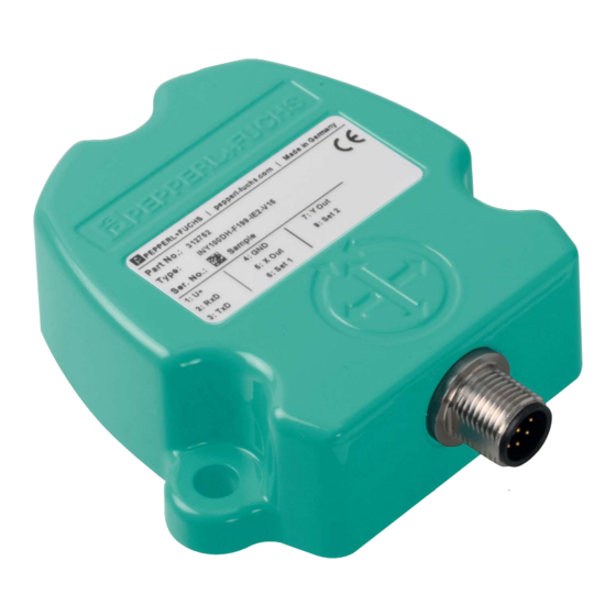
INX***DH-F199-B30-***,INY***DH-F199-B30-*** Product Description Product Description Use and Application INX***DH-F199-B30-*** and INY***DH-F199-B30-*** series inclination sensors detect and measure the tilt angle (inclination/slope/elevation) of an object in relation to the force of gravity. The basic principle behind these inclination sensors is a microelectromechanical systems (MEMS) sensor cell that is embedded in a fully molded application-specific integrated circuit (ASIC). -
Page 8: Installation
INX***DH-F199-B30-***,INY***DH-F199-B30-*** Installation Installation Instructions for Mechanical and Electrical Installation Observe the following instructions to ensure safe operation of the inclination sensor: Warning! Work must only be performed by trained and qualified personnel. Commissioning and operation of this electrical equipment must only be performed by trained and qualified personnel. -
Page 9: Mounting Instructions
INX***DH-F199-B30-***,INY***DH-F199-B30-*** Installation Mounting Instructions The inclination sensors are pre-calibrated devices that can be put into immediate operation following easy installation with a three point mount. The mounting surface must be flat and free of dust and grease. Depending on the sensor model, pay attention to the correct orientation of the sensor for inclination measurement when mounting. -
Page 10: Electrical Connection
INX***DH-F199-B30-***,INY***DH-F199-B30-*** Installation Electrical Connection The sensors are connected via M12 x 1, 5-pin connectors with MODBUS RTU. There are sensor models with one connector (V15) or two connectors (2V15). One-connector sensors have a male connector. Bus In Bus Out Signal n. -
Page 11: Modbus Rtu Device Registers And Codes
INX***DH-F199-B30-***INY***DH-F199-B30-*** MODBUS RTU Device Registers and Codes MODBUS RTU Device Registers and Codes INX***DH-F199-B30-*** and INY***DH-F199-B30-*** series sensors are flexible devices. All parameters are programmable via a MODBUS master. This enables remote configuration. This chapter consists of 2 major parts. One describing the methodology for putting an inclination sensor into operation and the other for programming an inclination sensor. -
Page 12: Device-Specific Registers
INX***DH-F199-B30-***INY***DH-F199-B30-*** MODBUS RTU Device Registers and Codes Device-Specific Registers Note! The following table describes the device-specific registers. Note that INX***DH-F199-B30-*** is a 1-axis measuring inclination sensor (x-axis) and INY***DH-F199-B30-*** is a 2-axis measuring inclination sensor (x-axis, y-axis) Note that data format of register "Current Postion Value Lower/Higher Register (x-Axis)" depends on the sensor type. - Page 13 INX***DH-F199-B30-***INY***DH-F199-B30-*** MODBUS RTU Device Registers and Codes Register Function Register Name Offset Access Code Data Byte Description and Values Default Offset Value Higher Register 000Ah 16 bits signed Read the offset value = – (x-Axis) Physical position - set position Offset Value Lower Register 000Bh 16 bits signed...
- Page 14 INX***DH-F199-B30-***INY***DH-F199-B30-*** MODBUS RTU Device Registers and Codes Example of Read Process Position value for 2–axis inclination sensor Request (Command) Response Name Value Name Value Device Address Device Address Function Code Function Code Starting Register 0000h Byte Count Address Number of Register 0004h Register 0 Value 0004h...
-
Page 15: Manufacturer-Specific Registers And Function Codes
INX***DH-F199-B30-***INY***DH-F199-B30-*** MODBUS RTU Device Registers and Codes Manufacturer-Specific Registers and Function Codes The following paragraph describes the user-defined function codes 0x44h (write) and 0x45h (read). User-defined function code 44h/45h is for less commonly used, off-line functions such as setting serial port parameters and changing the device address. Some MODBUS hosts cannot support this function code, but the frames can still be sent using a serial terminal program on a PC that can send binary data on the serial port. - Page 16 INX***DH-F199-B30-***INY***DH-F199-B30-*** MODBUS RTU Device Registers and Codes Example of Read Process Read Baud Rate Request (Command) Response Name Value Name Value Device Address Device Address Function Code Function Code Command Command Number of Bytes Number of Bytes xxxxh Response xxxxh Table 4.8 Example of Write Process Software power cycle...
-
Page 17: Device Identity
ID. The serial number is included as part of the product code. For example INY F199 Modbus S# 00202336. Name Object ID Access Data type Value Object length Vendor Name 00h 8 bits (ASCII) Pepperl+Fuchs 0Dh Product Code 8 bits (ASCII) IN* F199 (Includes Modbus Serial S#xxxxxxxx Number) Major Minor 8 bits (ASCII) SW-V01.00... -
Page 18: Modbus Communication Examples
INX***DH-F199-B30-***,INY***DH-F199-B30-*** MODBUS Communication Examples MODBUS Communication Examples Modbus Master Simulator Modbus Poll In the following chapters, the MODBUS master simulator "Modbus Poll" of "Witte Software Company" is used to display the command sequences and to establish MODBUS communication. "Modbus Poll" is a popular MODBUS simulator for testing and debugging slave devices. The software supports MODBUS RTU/ASCII and MODBUS TCP/IP. - Page 19 INX***DH-F199-B30-***,INY***DH-F199-B30-*** MODBUS Communication Examples Note! The following communication settings (Connection, Serial Settings) are only an example and have to be adapted to the existing hardware. Figure 5.2...
- Page 20 INX***DH-F199-B30-***,INY***DH-F199-B30-*** MODBUS Communication Examples Select the Test Center Click the "TC" symbol to open the "Test Center." Figure 5.3 The "Test Center" window with a command line opens. Figure 5.4 In the upper window, you can enter individually composed command sequences in the editor line in hexadecimal notation and send them to the MODBUS slave.
-
Page 21: Reading The Position Values Of A 2-Axis Inclination Sensor
INX***DH-F199-B30-***,INY***DH-F199-B30-*** MODBUS Communication Examples Reading the Position Values of a 2-Axis Inclination Sensor Note! The following description explains how to read the positon values of a 2-axis sensor. If you use a 1-axis sensor, you only have to read the x-axis registers. Device Registers Containing Position Values For device-specific registers See chapter 4.3. - Page 22 INX***DH-F199-B30-***,INY***DH-F199-B30-*** MODBUS Communication Examples 2. Click on the "Send" button to transmit the command including CRC to the inclination sensor. After receiving the command, the inclination sensor responds to the request. Figure 5.6 000-Tx: 7F 03 00 00 00 04 4E 17 >> command line with 2 byte CRC (4E 17) 001-Rx: 7F 03 08 00 00 0A 0F 00 00 10 02 D3 54 >>...
-
Page 23: Setting The Preset Values Of A 2-Axis Inclination Sensor
INX***DH-F199-B30-***,INY***DH-F199-B30-*** MODBUS Communication Examples Setting the Preset Values of a 2-Axis Inclination Sensor Note! The following description explains how to set the preset values of a 2-axis sensor. If you use a 1-axis sensor, you only have to set the x-axis registers. Device Registers Containing Preset Values For device-specific registersSee chapter 4.3. - Page 24 INX***DH-F199-B30-***,INY***DH-F199-B30-*** MODBUS Communication Examples Entering the Input Parameters 1. Enter the previous input parameters in hexadecimal form as a byte sequence in the com- mand-line window. Ensure that the "Add Check" and "CRC" options are activated so that the checksum CRC will be added automatically. Figure 5.7 2.
-
Page 25: Reading The Set Baud Rate
INX***DH-F199-B30-***,INY***DH-F199-B30-*** MODBUS Communication Examples Reading the Set Baud Rate The MODBUS inclination sensor also supports manufacturer-specific registers and function codes as described inSee chapter 4.4. However, not every MODBUS master supports these function codes. The following example to read the set baud rates shows how to use these function codes if possible. - Page 26 INX***DH-F199-B30-***,INY***DH-F199-B30-*** MODBUS Communication Examples 2. Click on the "Send" button to transmit the command including CRC to the inclination sensor. After receiving the command, the inclination sensor responds to the request. Figure 5.10 000-Tx: 7F 45 20 01 D0 25 >> command line with 2 byte CRC (D0 25) 001-Rx: 7F 45 20 01 03 64 9D >>...
- Page 27 Twinsburg, Ohio 44087 · USA Tel. +1 330 4253555 E-mail: sales@us.pepperl-fuchs.com Asia Pacific Headquarters Pepperl+Fuchs Pte Ltd. Company Registration No. 199003130E Singapore 139942 Tel. +65 67799091 E-mail: sales@sg.pepperl-fuchs.com www.pepperl-fuchs.com Subject to modifications / TDOCT-6236 Copyright PEPPERL+FUCHS • Printed in Germany 11/2018...
Need help?
Do you have a question about the INX DH-F199-B30 Series and is the answer not in the manual?
Questions and answers