Table of Contents
Advertisement
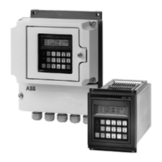
MAG-SM
Converter 50SM1000
Field Mount Housing and
19"-Design
Instruction Bulletin
D184B085U02 Rev. 01 / 06.2001
Software Revisions C.4X/X.3X & higher
Standard-Design EPROM
Part-No. D699B154U01
HART-Design EPROM
Part-No. D699B164U01
For Flowmeter Primaries with
AC Magnetic Field Excitation
Models: DS21_, DS4_, 10DS2111,
10DS2112, 10DS3111, 10DS3112,
10DS3121, 10DI1425, 10D1422
Advertisement
Table of Contents

Related Manuals for ABB MAG-SM


Summary of Contents for ABB MAG-SM
- Page 1 MAG-SM Converter 50SM1000 Field Mount Housing and 19“-Design Instruction Bulletin D184B085U02 Rev. 01 / 06.2001 Software Revisions C.4X/X.3X & higher Standard-Design EPROM Part-No. D699B154U01 HART-Design EPROM Part-No. D699B164U01 For Flowmeter Primaries with AC Magnetic Field Excitation Models: DS21_, DS4_, 10DS2111,...
- Page 2 This Instruction Bulletin contains information relating to the assembly and installation of the instrument and its specifications. ABB Automation Products reserves the right to make hardware and software improvements without prior notice. Any questions which may arise that are not specifically answered by these instructions should be referred to our main plant in Göttingen, Germany Tel 49-551/905-0...
- Page 3 (GefStoffV, 17 General Protection Responsibility), a responsibility to protect his employees, we must make note that a) all flowmeter primaries and/or flowmeter converters which are returned to ABB Automation Products for repair are to be free of any hazardous materials (acids, bases, solvents, etc.).
-
Page 5: Table Of Contents
Contents Page Functional Description ........... . . 1 Assembly and Installation . - Page 6 Analog Board MAG-SM ........
-
Page 7: Functional Description
„Load data from ext. EEPROM“ with ENTER. See also Page 26. Instruction Bulletin Flowmeter Primary Converter MAG-SM D184B064U01 Rev. 02 50SM1000 D184B085U01 Rev. 01 Specification Sheet MAG-SM D184S034U01 Rev. 01... -
Page 8: Dimension Drawings
Electromagnetic Flowmeter Converter Dimension Drawings Field Mount Housing Cable Connector M20 x 1.5 Mounting Dimensions 106,4 35,3 35.3 106.4 Control Card (only for contact output - relay) 426,72 426.72 465,1 465.1 Min. Distance for Cable Entry 19”-Insert with Card Frame 3 x Blind Plugs Pg 13.5 Panel Cutout 2 x 2 Clamp Brackets... -
Page 9: Electrical Interconnections, Converter
Electromagnetic Flowmeter Converter Electrical Interconnections, Converter 2.4.3 Power The connection voltage and the current for the flowmeter 2.4.1 Supply Power Connections primary are listed on the Instrument Tag. The cable cross- The supply power, which should conform to the specifications section for the supply power and the fuse size must be listed on the instrument tag, is connected to terminals L (Phase) compatible (VDE 0100). -
Page 10: Signal And Reference Voltage Cable Connections
Inerconnection Diagrams to the flowmeter primary and the converter. Note: The supply voltage for the MAG-SM with a preamplifier is The flowmeter system complies with the NAMUR- connected to terminals -U and +U, instead of 1S and 2S. If the Recommendations 5/93 “Electromagnetic Compatibility... -
Page 11: Cable Connection Area
Electromagnetic Flowmeter Converter 2.4.5 Cable Connection Area The leads of the signal cable are to be routed in the shortest manner to the connection terminals. Loops are to be avoided, (see Figs. 4 and 5). Cable Connection Area with Screwless Spring Loaded Terminals 2 2S 3 1S 1... - Page 12 Electromagnetic Flowmeter Converter ≥ 20” (DN 500) 14” – 16” (DN 350 – DN 400) Standard Design Supply Power Signal Cable (FP) 16 3A 16 3a R905 R906 R904 Spule1 Spule2 R903 Connection Box with Preamplifier for Fluids with Low Conductivity ≥ 0.5 µS/cm Terminal Designation Connection 1 + 2...
-
Page 13: Interconnection Diagrams
Electromagnetic Flowmeter Converter Interconnection Diagrams 2.5.1 Interconnection Diagrams, Flowmeter Primaries 1/25” - 16” [DN 1 - DN 400] with Converter in Field Mount Housing or 19”-Design Note: Select the flowmeter primary model number in the parameter “Primary Type” in Submenu “Primary” in the converter. Switch S901 on the connection board of the converter must be opened (Connection Board, see Pages 38/39/40). - Page 14 V5, V6; Function 55, 56 forward. Shielded signal cable (10 m included with shipment from ABB), ABB Part No. D173D018U02. Supply voltage for flowmeter primaries with preamplifiers (1/25” - 5/16” [DN 1 - DN 8] always include a preamplifier), terminals +U, -U.
-
Page 15: Interconnection Diagram, Flowmeter Primaries 20" - 40"[Dn 500 To Dn 1000] With Converter In Field Mount Housing Or 19"-Design (Starting With 10Ds3111D)
Electromagnetic Flowmeter Converter 2.5.2 Interconnection Diagram, Flowmeter Primaries 20” - 40”[DN 500 to DN 1000] With Converter in Field Mount Housing or 19”-Design (starting with 10DS3111D) Note: WARNING: Select the flowmeter primary model number in the parameter The magnet coils are supplied from the line, “Primary Type”... - Page 16 Scaled pulse output, optocoupler, U terminals V5, V6; Function 55, 56 forward. Shielded signal cable (10 m included with shipment from ABB), ABB Part No. D173D018U02. *) Scaled pulse output, active or passive, pulse width can be set from 0.032 to 2000 ms.
-
Page 17: Retrofitting
Electromagnetic Flowmeter Converter Retrofitting Interconnection Diagrams can be used for the converter The MAG-SM in a field mount housing or in a 19”-Design can in a field mount housing or in a 19”-Design. also be used to operate the electromagnetic flowmeter primaries Model 10D1422. - Page 18 Electromagnetic Flowmeter Converter Supply power, see Instrument Tag. Magnet coil supply from line. External zero return, passive, over contact with internal voltage supply terminals U2 (+24 V DC) and 22. Switch S902 closed. External totalizer reset, passive over contact with internal voltage supply terminals U2 (+24 V DC) and 31.
-
Page 19: Interconnection Diagram For Retrofitting Converter 50Sm1000 In 19"-Design; Flowmeter Primary 10D1422
Electromagnetic Flowmeter Converter 2.6.2 Interconnection Diagram for Retrofitting Converter 50SM1000 in 19”-Design; Flowmeter Primary 10D1422 Note: WARNING: Select the flowmeter primary model number in the The magnet coils are supplied from the line, parameter “Primary Type” in Submenu “Primary” in the not from the converter. - Page 20 Electromagnetic Flowmeter Converter Supply power, see Instrument Tag. Magnet coil supply from line. External zero return passive, over contact with internal voltage supply, terminals U2 (+24 V DC) and 22. Switch S902 closed. External totalizer reset, passive over contact with int. voltage supply, terminals U2 (+24 V DC) and 31.
-
Page 21: Interconnection Examples For Peripherals
Electromagnetic Flowmeter Converter Interconnection Examples for Peripherals Scaled Pulse Output, active Scaled Pulse Output, passive, optocoupler internal external internal external (58) (58) 24 V+ 24 V+ Reverse (57) Reverse (57) Forward (56) (56) 24 V+ 24 V+ Forward (55) (55) Current Output Alarm Output, optocoupler Alarm Output, relay... -
Page 22: Start-Up
Electromagnetic Flowmeter Converter Start-Up General Information • If there is no indication of flowrate it may be possible that the Preliminary Checks singal cable connections are reversed. Interchange the Before turning on the instrument check that the leads connected to terminals 1 and 1S with those at 2 and •... -
Page 23: Data Entry
Electromagnetic Flowmeter Converter Data Entry A totalizer overflow occurs whenever the totalizer value reaches 9,999,999 units. When the totalizer value in one of the General Description flow directions is greater than 9,999,999 units, the flow direction 5.1.1 Data Entry Information symbol (→... -
Page 24: Data Entry Information
Electromagnetic Flowmeter Converter 3.1 The computer checks the data entered after the 5.1.1 Data Entry Information » ENTER « key is pressed. If the data value is outside of Special programming knowledge is not required for entering the allowable setting range an error meessage is displayed data. -
Page 25: Parameter Overview Standard Software (Hart-Protocol See Page 33) And Data Entry
Electromagnetic Flowmeter Converter 5.2. Parameter Overview Standard Software (HART-Protocol see Page 33) and Data Entry Submenu/Parameter Entry Type Comments from table/numeric Data can only be entered when the program protection has been * Prog. Protection* turned off. on / off * Prog. - Page 26 Electromagnetic Flowmeter Converter Submenu/Parameter Entry Type Comments Pulse factor for int. and ext. flow totalization, numeric Range 0.001–1000 pulses per selected flow unit, Pulse max. count frequency 10 kHz. 1.000 Note: The max. count frequency and the pulse factor are checked by the software, if out of range Error 40 “Frequency >10 kHz”...
- Page 27 Electromagnetic Flowmeter Converter Submenu/Parameter Entry Type Comments from table/numeric Exit the submenu Submenu C/CE Units Selectable flowrate units ml/s, ml/min, ml/h, Ml/h, Ml/min, Ml/day, lb/s, lb/min, lb/h, Units Qmax uton/min, uton/h, uton/day, l/s, l/min, l/h, hl/s, hl/min, hl/h, ENTER /s, m /min, m /h, igps, igpm, igph, mgd, gpm, gph, bbl/s, bbl/min, bbl/h, bls/day, bls/min, bls/h, kg/s, kg/min,...
- Page 28 Electromagnetic Flowmeter Converter Submenu/Parameter Entry Type Comments Help text information, exit by pressing C/CE. ↑ ↓ C/CE STEP After pressing the STEP-key a clear text description for each error . 0 . (set) code number is displayed. Active errors are indicated by the text Empty pipe “(set)”.
- Page 29 Report Printer Standard ABB 55DE1000 can be selected. This parameter is only displayed when a printer protocol and the ABB 55DE1000 Printer have both been selected. Print time Entries for the Protocol Printer: Year, Month, Day, Hour, Minute...
- Page 30 Electromagnetic Flowmeter Converter Submenu/Parameter Entry Type Comments ! Note: from table/numeric For trouble free operation the function “Detector Empty Pipe” Submenu µ should only be used for fluid conductivities above 20 S/cm and Detector e.pipe meter sizes 3/8” [DN 10] and up. Not available for MAG-CS. off = Empty pipe detector turned off Detector e.pipe on = When the metering tube empties, a message is...
- Page 31 Electromagnetic Flowmeter Converter Submenu/Parameter Entry Type Comments See forward direction overflow counter Overflow ← R The totalizer function is automatically set as a function of the selections in the “Operating Mode” submenu. Operating mode Standard = Totalizer function Standard; Tot. function Operating mode Piston Pump = Totalizer function Standard Difference totalizer...
- Page 32 An alphanumeric meter identification TAG-Number, with up to 16 TAG Number characters, can be entered utilizing lower and upper case letters and numbers. numeric Only for ABB Fischer & Porter Service. Service Code...
-
Page 33: Parameter Entry (Additional Information)
Electromagnetic Flowmeter Converter Submenu Function Test Parameter Entry (Additional Information) Numeric Entries only for I and F 5.3.1 User Programmable Units With this function it is possible to program any desired Submenu units in the converter. The following three parameters are included in this function: Function Test a) Units factor... -
Page 34: Communication With The Field Instruments Using Operator And Monitoring Stations
Two different communication technologies are available for ASCII-Code 31 hex characters and monitors the received data exchange between the MAG-SM electromagnetic characters. On the left side of the display the number of flowmeter and a process control system, computer, PC or SPC. - Page 35 In- and outgoing cables connected to the same terminals. The name of the GSD file is ABB_6666.GSD and is included with the shipment. For a detailed description of the Data Link see the separate Document ABB Part No. D184B093U03. (SPS) With Bus...
- Page 36 “External Totalizer Reset”. they are compatible. The data and time can also be printed when using the ABB- An incorrect character set is processed if an incorrect printer Printer (55DE1000). The time can be set in the Printer Clock type is selected resulting in an improperly printed report.
-
Page 37: Hart®-Protocol
4–20 mA current signal into a digital output signal per Bell 202 with a RS 232C output to the PC. In addition, the MAG-SM can also be accessed and configured from a handheld terminal Type 275. A parallel connection is made to the 4–20 mA current output. - Page 38 Electromagnetic Flowmeter Converter Process Level Field Level Process Control Level 4–20 mA 4–20 mA Supply Power 4–20 mA Press. Converter 4–20 mA Swirl 4–20 mA Vortex 4–20 mA 6 Vortex 4–20 mA 19”-Design min = 250 Ohm Mass Control System Field Multiplexer Project Station RS485...
-
Page 39: Parameter Overview Hart-Protocol, Data Entry, See Pages 19 To 26
Electromagnetic Flowmeter Converter 5.5.3 Parameter Overview HART-Protocol, Data Entry, see Pages 19 to 26 Submenu/Parameter Submenu/Parameter Entry Type Comments Prog. Protection Density 1.0000 g/cm3 Language Display in English l/min Meter size System zero 25 mm 1 in 0.0000 Units Qmax Submenu l/min Operating mode... - Page 40 Electromagnetic Flowmeter Converter Submenu/Parameter Entry Type Comments Submenu Function Test Submenu Detector e.pipe Totalizer > F reset Overflow > F Totalizer < R reset Overflow < R Error register . . . 3 ..Multiplex Disp. Load data from ext. EEPROM Store data in ext.
-
Page 41: Maintenance
Electromagnetic Flowmeter Converter Maintenance 6.2.1 Maintenance The converter is maintenance free. General Note: Please observe the “Introductory Safety Notes for the WARNING: EMF System” if a converter must be returned to the fac- The are electrostatic sensitive parts on the tory for repairs. -
Page 42: Testing The Metering System
Electromagnetic Flowmeter Converter 6.3.2 Testing the Metering System WARNING: Contact hazards exist when the housing cover is removed and the power is turned on ! These tasks should only be performed by trained personnel. Does the supply power agree with the values listed on the Solder correct jumpers for the required voltage, converter Instrument Tag? see Fig.20. -
Page 43: Block Diagram
Electromagnetic Flowmeter Converter Block Diagram Fig.16 Block Diagram... -
Page 44: Connection Board, Field Mount Housing 50Sm1000
Electromagnetic Flowmeter Converter Connection Board, Field Mount Housing 50SM1000 Fig.17 Connection Board, Field Mount Housing... -
Page 45: Connection Board 19"-Design 50Sm1000
Electromagnetic Flowmeter Converter Connection Board 19”-Design 50SM1000 Terminal designations for flow- S901-Switch opened: S901-Switch closed: Jumper 1 + 2 for flowmeter For flowmeter primaries For flowmeter primaries meter primaries with preamplifiers primaries without preamplifiers 10DI1425 ≤ 16”[DN 400} 10DI1425 ≥ 20”[DN 500] U-, 1, 2, U+ Jumper 7 + 8 for flowmeter 10DS2111/3111/3121... - Page 46 Model 10DS3112 Terminals F1/F3 L904 C909 C920 Fuse 2 A-T C911 C908 ABB-Part No. D151B001U04 L/N/PE 100/110/120/240 V AC For Fwd. Pulse 0-10 kHz Control Board 1L1/1L2/PE 24 V AC Circuit board trace break Tr.3 Optocoupler Design Jumper Br.9 Fig.19...
-
Page 47: Analog Board Mag-Sm
Electromagnetic Flowmeter Converter Analog Board MAG-SM EEx-Design 10DS3112: EEx-Design 10DS3111: 12 V coil voltage (F1/F3) 48 V coil voltage (M1/M3) Jumper BR108 not used, Jumper BR108 not used, Fuse F102 Type 1.6 A Fuse F102 Type 0.5 A Mini Fuse TR5-M 19371K Mini Fuse TR5-M 19371K ABB-Part No. -
Page 48: Digital Board Mag-Sm
Electromagnetic Flowmeter Converter Digital Board MAG-SM C204 C203 C225 S206 S207 C230 V201 V202 C202 G202 R220 C229 G201 C224 V207 D209 D213 R224 R231 +12V R221 C226 R219 R225 D210 R202 C223 AGNO R218 R228 V204 V209 R216 C205... -
Page 49: Assembled Module
Electromagnetic Flowmeter Converter Assembled Module Amplifier and Integrator Module amplified Output Phase Selective Rectifier approx. 5 V Voltage values based on = 100 mV rms. Pot for Phase Pot for Setting flow signal symmetry Pot for reference Flow signal ampli- voltage fied approx. - Page 50 Electromagnetic Flowmeter Converter Detector Empty Pipe Module Fig.24 Empty Pipe Module (Option) Pulse Amplifier Module with Active Output Pulse Amplifier Module with Relay Output Fig.25 Pulse Output Module Active or Relay...
- Page 51 Electromagnetic Flowmeter Converter Pulse Amplifier Module with Optocoupler Output Serial Data Link RS 485 (RS 422) Fig.26 Pulse Output Module Optocoupler, Data Link RS 485...
-
Page 52: Replaceable Parts List, Converter 50Sm1000 Field Mount Housing
Electromagnetic Flowmeter Converter Replaceable Parts List, Converter 50SM1000 Field Mount Housing 16/17 11/10 19/20 13/14 6/7/8 4 / 5 Fig.27 Description Part No. Housing - lower section D612A109U16 Gasket D333F011U01 Gasket D333F013U01 Seal plug D114A001U13 Cable connector M20 x 1.5 D150A008U15 Clamp bracket D108A003U02... -
Page 53: Replaceable Parts List, Converter 50Sm1000 19"-Design
Electromagnetic Flowmeter Converter Replaceable Parts List, Converter 50SM1000 19”-Design 8 / Code card 5 / 6 Front plate Top View Fuse 2 A-T Part No. D151B001U04 Jumper 1, 2 without preamplifier (1S, 2S) Jumper 7, 8 with preamplifier (U+, U-) Rear View Connection Board Relay Design Fig.28... -
Page 54: Safety Information Per En 61010-1
• For overhaul or repair only original replacement parts obtained from ABB are to be used. • The voltage supply and the circuits for the excitation coils in the flowmeter primary and hazardous to personnel contact. -
Page 55: Additional Information For Profibus Dp
Electromagnetic Flowmeter Converter Additional Information for Profibus DP GSD File (Instrument Data Base File) The name of the GSD file is FP6666.GSD and is included with the shipment. Parameter Entry Submenu .Data link The communication mode Profibus DP is selected in the Communication Submenu Data Link. -
Page 56: Additional Information For The Pulse Output
Electromagnetic Flowmeter Converter Additional Information for the Pulse Output The scaled pulse output can be ordered as a 2-channel pulse output, separate for forward and reverse in an active (24 V DC) or passive (optocoupler) design. When configuring the parameter the following settings must be entered. Parameter Entry Pulse Factor The pulse factor is the number of output pulses for one measured flowrate unit. -
Page 57: Additional Information For Piston Pump/Pulsation Operating
Electromagnetic Flowmeter Converter Additional Information for Piston Pump/Pulsation Operating Parameter Entry The primary applications for the AC field flowmeters is for fast measurement processing of continuous flows for single or multiphase fluids. If pulsation dampeners can be installed then the DC field flowme- Submenu ters can usually be utilized. -
Page 58: Parameter Setting Overview And Flowmeter Design Options
Electromagnetic Flowmeter Converter 10. Parameter Setting Overview and Flowmeter Design Options Meter Location: TAG-No.: Primary Type: Converter Type Order No.: Instrument No.: Order No.: Instrument No.: Fluid Temp.: Voltage Supply: Liner: Electrodes: Excitation Frequency: System Zero: Parameter Setting Range Prog. Protection Code 0–255 ( 0 = factory setting) Language German, English, French, Finnish, Spanish, Italian,... - Page 59 Control Processing Unit Direct access key Submenu Display The diode blinks when a CPU (Processor) failure is Display Number 7 detected. If this occurs contact the ABB-Service Department. Double function key Direct access key Damping (Response Time) Damp. Number 8...
- Page 60 ABB Automation Products GmbH Dransfelder Str. 2, D-37079 Goettingen Tel.: +49 (0) 5 51 9 05 - 0 Fax: +49 (0) 5 51 9 05 - 777 http://www.abb.com...
Need help?
Do you have a question about the MAG-SM and is the answer not in the manual?
Questions and answers