Table of Contents
Advertisement
Quick Links
Advertisement
Table of Contents

Related Manuals for Cardinal 225NEST

Summary of Contents for Cardinal 225NEST
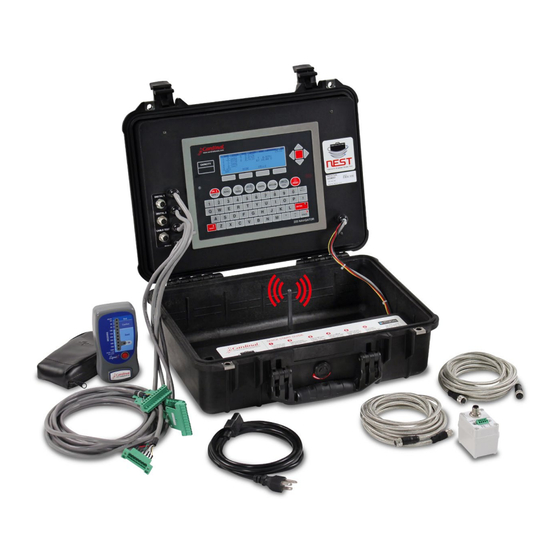
- Page 1 225NEST Operation Manual For Analog and Digital Systems...
- Page 3 Before using this product, read this manual and pay special attention to all "NOTIFICATION" symbols: ELECTRICAL STATIC IMPORTANT WARNING SENSITVE SERIAL NUMBER _____________________________________ DATE OF PURCHASE _________________________________ PURCHASED FROM ___________________________________ ____________________________________________________ RETAIN THIS INFORMATION FOR FUTURE USE 4400-0020-0M Rev C 225NEST Operation...
- Page 4 CAUTION: RISK OF EXPLOSION IF BATTERY IS REPLACED BY AN INCORRECT TYPE. DISPOSE OF USED BATTERIES ACCORDING TO THE INSTRUCTIONS. ATTENTION: RISQUE D'EXPLOSION SI LA BATTERIES EST REMPLACE'E PAR UN TYPE INCORRECT. REJETEZ LES BATTERIES UTILISE'ES SELON LES INSTRUCTIONS. 4400-0020-0M Rev C 225NEST Operation...
-
Page 5: Table Of Contents
CELLS Key ..........Page 21 4400-0020-0M Rev C 225NEST Operation... - Page 6 Analog Scale Commands ........Page 39 Commands Common to Both Digital and Analog Scales ... . . Page 47 4400-0020-0M Rev C 225NEST Operation...
-
Page 7: Introduction
INTRODUCTION The 225NEST is a diagnostic tool for use with Cardinal ARMOR Digital Truck Scales with SMARTCELL load cells and ARMOR Truck Scales with analog load cells and junction boxes. The NEST provides fast, accurate and ultra-portable truck scale diagnostics. Quickly test individual load cells, the load cell cables, and check the home run and weight indicator connections. -
Page 8: Armor Digital Truck Scale With Smartcell Load Cells
See the ANALOG SCALE DIAGNOSTICS section, CELLS KEY in the KEYPAD FUNCTIONS section to see how to change the load cell parameters. 4400-0020-0M Rev C 225NEST Operation... -
Page 9: Select Test Mode
SELECT TEST MODE The 225NEST is a diagnostic tool for use with Cardinal ARMOR Digital Truck Scales with SMARTCELL load cells and ARMOR Truck Scales with analog load cells and junction boxes. To Select the Test Mode 1. Press the ON|OFF key to apply power to the NEST. -
Page 10: Display Contrast Adjustment
2. Repeat pressing the SPACE key to reduce the contrast to the desired level. 3. When the LCD contrast is at the desired level, stop pressing the SPACE key and release the SHIFT key to save the setting. 4400-0020-0M Rev C 225NEST Operation... -
Page 11: Digital Scale Diagnostics
DIGITAL SCALE DIAGNOSTICS 4400-0020-0M Rev C 225NEST Operation... -
Page 12: Nest Digital Ports And Cable Test Remote
Cable Test Port Port (CAN Bus 2) CABLE TEST CABLE TEST REMOTE Digital Cable Test Port CABLE TEST Cable Outer Metal Cover Clip CABLE TEST Cable Outer Metal Cover Clip Wire NEST Digital Ports 4400-0020-0M Rev C 225NEST Operation... -
Page 13: Smart Scale Tester
This allows the test to check for an internal wire shorted to the outer metal cover. 4. Press the 1 key, and then the ENTER key. 5. The display will change to show the cable test screen. NOM. ACTUAL PASS/FAIL 0.00V 0.00V PASS 15.16 0.000 AUTO N EXT EXIT 4400-0020-0M Rev C 225NEST Operation... -
Page 14: Auto Load Cell Cable Test
1.60V to 1.70V 2.06V 2.01V to 2.11V 2.48V 2.43V to 2.53V 2.89V 2.84V to 2.94V 3. Press the EXIT key to exit the manual load cell cable test, and return to the SMART SCALE TESTER screen. 4400-0020-0M Rev C 225NEST Operation... -
Page 15: How To Test The Homerun Cable
10. Next, on the NEST keypad, press the 1 key, and then the ENTER key. 11. The display will change to show the cable test screen. NOM. ACTUAL PASS/FAIL 0.00V 0.00V PASS 15.16 0.000 AUTO N EXT EXIT 4400-0020-0M Rev C 225NEST Operation... -
Page 16: Auto Homerun Cable Test
1.60V to 1.70V 2.06V 2.01V to 2.11V 2.48V 2.43V to 2.53V 2.89V 2.84V to 2.94V 3. Press the EXIT key to exit the manual Homerun cable test, and return to the SMART SCALE TESTER screen. 4400-0020-0M Rev C 225NEST Operation... -
Page 17: Reconnect The Homerun Cable
The release bar will return to its original position, locking the wire in place. Press Down Here Insert Wire Here 6. Repeat the procedure until all five wires are in place. 7. After all terminations have been made, remove any excess cable from the enclosure. 4400-0020-0M Rev C 225NEST Operation... - Page 18 DO NOT USE TOOLS! Finger-tighten only! 10. Re-insert the 225D power cord into the wall outlet. 11. Press the ON/OFF key on the keypad to turn on the 225D indicator. 12. The 225D indicator is ready for normal operations. 4400-0020-0M Rev C 225NEST Operation...
-
Page 19: Cell Test
4. The NEST will then check both communication loops. CELL TEST 15.16 Testing CAN bus 1 0.040 CELL TEST 15.16 Testing CAN bus 2 0.040 5. Next, it will test the analog section. CELL TEST 15.16 Testing analog 0.040 4400-0020-0M Rev C 225NEST Operation... - Page 20 8. When the load cell test has completed, it will display Pass or Fail on the screen. CELL TEST 15.16 Cell Test: Pass 0.040 START EXIT 9. Press the EXIT key to return to the SMART SCALE TESTER menu. 4400-0020-0M Rev C 225NEST Operation...
-
Page 21: Analog Scale Diagnostics
ANALOG SCALE DIAGNOSTICS 4400-0020-0M Rev C 225NEST Operation... -
Page 22: Nest Analog Testing Cables
Load Cells 7-12 (if necessary) 3. Press the ON|OFF key to apply power to the NEST. 4. The display will show the Cardinal Logo, the model number and software revision, and then change to the TESTER TYPE screen. TESTER TYPE 1. -
Page 23: Signals Display
12 correspond to the load cell signals SIG1 through SIG12. T is the signal from the junction box summing circuitry. EX is the 225NEST’s excitation voltage. The right side of the display gives status information about the 225NEST. PWR indicates the voltage being provided to the 225NEST. -
Page 24: Minimum-Maximum Display
The ^SCROLLv key is used to scroll the display when there are more signals than can be displayed on the screen. The ZERO key is used to set a new starting point for minimum- maximum readings. 4400-0020-0M Rev C 225NEST Operation... -
Page 25: Signals Minus Zero Reference Display
The DAC, MODE, and CELLS soft keys have the same function as on the signals display. The ^SCROLLv key is used to scroll the display when there are more signals than can be displayed on the screen. The ZERO key is used to set a new zero reference. 4400-0020-0M Rev C 225NEST Operation... -
Page 26: Keypad Functions
Press this key to scroll the displayed signals up. Hold down the SHIFT key and press this key to scroll the displayed signals down. 4400-0020-0M Rev C 225NEST Operation... -
Page 27: Cells Key
Otherwise, use the numeric keys to enter a new cell capacity. As each number key is pressed, the previously entered digits will scroll to the left. When the display shows the desired cell capacity, press the ENTER key, and the display will return to the Cells Menu. 4400-0020-0M Rev C 225NEST Operation... - Page 28 When the display shows the desired interval, press the ENTER key, and the display will return to the Cells Menu. Press the (Navigation Keys UP Arrow) to exit the Cells Menu and return to the previous analog testing screen. 4400-0020-0M Rev C 225NEST Operation...
- Page 29 Response (if display mode is CELL ID’s): aaaaaaaa,bbbbbbbb,... are the cell IDs) Response (if display mode is cell millivolts): <lf>D4,aaaaaaaa,bbb.bbbb,cccc,...<cr> aaaaaaaa bbb.bbbb cccc is the cell ID, is the cell millivolts, and is the cell status) 4400-0020-0M Rev C 225NEST Operation...
- Page 30 <lf>D10,MAX WT COUNT,ANLG ERR COUNT,MAX TEMP,MIN TEMP, mV MAX-MIN,WT MAX-MIN,mV-DL,WT-DL<cr> Response (if display mode is cell maximum weight count): <lf>D11, aaaaaaaa,bbbbbbbb,cccc,...<cr> aaaaaaaa bbbbbbbb cccc is the cell ID, is the cell maximum weight count, and the cell status) 4400-0020-0M Rev C 225NEST Operation...
- Page 31 Get Displayed Readings Alternate Command <enq> Command: <lf>Xm<cr> Response: same as for 4400-0020-0M Rev C 225NEST Operation...
- Page 32 13 Cell maximum temperature 14 Cell minimum temperature 15 Cell millivolts maximum-minimum 16 Cell weight maximum-minimum 17 Cell millivolts-zero reference 18 Cell weight-zero reference <lf>MODE=Dn<cr> Response (valid mode): is the selected display mode. <lf>?<cr> Response (invalid mode): 4400-0020-0M Rev C 225NEST Operation...
- Page 33 Response (if display is in millivolts or weight minimum-maximum mode or millivolts or weight minus zero reference mode): <lf>OK<cr> Response (if display is not in millivolts or weight minimum-maximum mode or millivolts or weight minus zero reference mode): <lf>?<cr> 4400-0020-0M Rev C 225NEST Operation...
- Page 34 8. The most significant bit of the message ID will be 1, indicating 29-bit ID. The cell ID can be determined by “anding” the message ID with 1FFFFFFF, hexadecimal) 4400-0020-0M Rev C 225NEST Operation...
- Page 35 <lf>CANTERMn=x<cr> Response: Get VP1 (V+ Bus) Control <lf>Xj<cr> Command: <lf>VP1=n<cr> Response: if VP1 is enabled, if VP1 is disabled) Set VP1 (V+ Bus) Control <lf>XJn<cr> Command: to enable VP1, to disable VP1) <lf>VP1=n<cr> Response: 4400-0020-0M Rev C 225NEST Operation...
- Page 36 “MANUAL” if test is in manual mode, “STOPPED” if test is in auto mode stopped, or “RUN” if test is in auto mode running) Get Cable Tester Binary Out <lf>Xt<cr> Command: <lf>CABLE=n<cr> Response: through Set Cable Tester Binary Out <lf>XTn<cr> Command: through <lf>CABLE=n<cr> Response: 4400-0020-0M Rev C 225NEST Operation...
- Page 37 SIG9 reading. sig10 is load cell SIG10 reading. sig11 is load cell SIG11 reading. sig12 is load cell SIG12 reading. sigT is junction box summing circuitry reading. is excitation voltage reading. 4400-0020-0M Rev C 225NEST Operation...
- Page 38 SIG4 minimum reading. sig4max is load cell SIG4 maximum reading. sig4max-min is load cell SIG4 maximum reading minus minimum reading. sig5 is load cell SIG5 reading. sig5min is load cell SIG5 minimum reading. 4400-0020-0M Rev C 225NEST Operation...
- Page 39 4400-0020-0M Rev C 225NEST Operation...
- Page 40 SIG6 zero reference. sig6-zero is load cell SIG6 reading minus SIG6 zero reference. sig7 is load cell SIG7 reading. sig7zero is load cell SIG7 zero reference. sig7-zero is load cell SIG7 reading minus SIG7 zero reference. 4400-0020-0M Rev C 225NEST Operation...
- Page 41 The excitation voltage reading is six characters wide, including the embedded decimal point. If the NEST analog to digital converter is not functioning, the readings will be replaced by: ERROR Get Displayed Readings Alternate Command <enq> Command: <lf>Xm<cr> Response: same as for 4400-0020-0M Rev C 225NEST Operation...
- Page 42 (in the range 1 to 12). <lf>?<cr> Response (number of cells out of range): Get Number of Cells Being Displayed <lf>Xc<cr> Command: <lf>CELLS=xx<cr> Response: represents the number of cells being displayed (in the range 1 to 12). 4400-0020-0M Rev C 225NEST Operation...
- Page 43 DAC is set to (in the range 0 to 16383). <lf>?<cr> Response (DAC value out of range): Get DAC Setting <lf>Xd<cr> Command: <lf>DAC=xxxxx<cr> Response: xxxxx represents the value the DAC is set to (in the range 0 to 16383). 4400-0020-0M Rev C 225NEST Operation...
- Page 44 Reference for Signals Minus Zero Reference Display <lf>XZ<cr> Command: Response (if display is in minimum-maximum mode or signals minus zero reference mode): <lf>OK<cr> Response (if display is not in minimum-maximum mode or signals minus zero reference <lf>?<cr> mode): 4400-0020-0M Rev C 225NEST Operation...
- Page 45 Response: <lf>B<cr> Command: <lf>MFG:Cardinal Scale Mfg. Co.<cr> Response: <lf>B<cr> Command: <lf>MOD:225NEST<cr> Response: <lf>B<cr> Command: <lf>REV:x.x.xx<cr> Response: x.x.xx represents the version of the 225NEST firmware) <lf>B<cr> Command: <lf>END:<cr> Response: Get Information Reset Serial <lf>I<cr> <esc> Command: Command: <lf>SMA:2/1.0<cr> Response: none Response: <lf>N<cr>...
- Page 46 STATEMENT OF LIMITED WARRANTY WARRANTY TERMS Cardinal Scale Manufacturing Company warrants the equipment we manufacture against defects in material and workmanship. The length and terms and conditions of these warranties vary with the type of product and are summarized below:...
- Page 47 This warranty sets forth the extent of our liability for breach of any warranty or deficiency in connection with the sale or use of our product. Cardinal will not be liable for consequential damages of any nature, including but not limited to loss of profit, delays or expenses, whether based on tort or contract.
- Page 48 Cardinal Scale Mfg. Co. 203 E. Daugherty, Webb City, MO 64870 USA Ph: 417-673-4631 or 1-800-641-2008 Fax: 417-673-2153 www.cardinalscale.com Technical Support: 1-866-254-8261 Printed in USA E-mail: tech@cardet.com 4400-0020-0M Rev C 01/19 4400-0020-0M Rev C 225NEST Operation...
Need help?
Do you have a question about the 225NEST and is the answer not in the manual?
Questions and answers