Table of Contents
Advertisement
Quick Links
Advertisement
Table of Contents

Related Manuals for Cardinal GUARDIAN

Summary of Contents for Cardinal GUARDIAN
- Page 1 The GUARDIAN ® HYDRAULIC FLOOR STAND TANK/HOPPER ASSEMBLIES OWNER'S MANUAL 1780-M057-O1 Rev C 203 E. Daugherty, Webb City, MO 64870 USA 11/14 Ph: 417-673-4631 Fax: 417-673-2153 Printed in USA www.cardinalscale.com Technical Support: Ph: 866-254-8261 tech@cardet.com...
- Page 2 1780-M057-O1 Rev C Hydraulic Floor Stand Tank/Hopper...
-
Page 3: Table Of Contents
TABLE OF CONTENTS Introduction ............. . Page 1 Site Preparation . -
Page 5: Introduction
The totalizer enclosure contains a simple manifold assembly and a Cardinal PTG-3K Pressure Transducer for each load cell. The Pressure transducers convert the hydraulic pressure generated by the load cell to an analog signal that is easily trimmed and summed. -
Page 6: Installation
INSTALLATION In most installations it is advisable to locate and install the cells before the vessel or weighbridge is set in place. If the cell stand assemblies are installed with the vessel or weighbridge in place, extreme care should be taken to ensure that the stability of the vessel or weighbridge is maintained during installation of the load cell stands. - Page 7 INSTALLATION, CONT. Next, mount the totalizer enclosure on a wall as close to the digital weight indicator as possible. The totalizer enclosure should be mounted with at least 24 inches of clearance below it to allow room to connect the hydraulic tubes running from the cells to the bulkhead fittings. The 2 inch conduit from the scale should be stubbed up directly under the left side of the totalizer enclosure for the easiest installation.
- Page 8 INSTALLATION, CONT. Load Cell Tubes Suppressor Package Manifold Fittings Figure No. 4 (3 & 4-Cell Totalizer Enclosure with Suppressor Package) Connect the load cell tubes to the totalizer enclosure bulkhead fittings. The tubes are normally installed with the tube for cell #1 being installed toward the front of the enclosure with the odd cells on the left and even cells on the right.
-
Page 9: Gauging Sst Hydraulic Load Cells
INSTALLATION, CONT. Gauging SST Hydraulic Load Cells Filling and bleeding the system is a very simple procedure. Begin by filling the pressure pump with oil and attaching it to the inlet port located on the outside, bottom right side of the totalizer enclosure. - Page 10 INSTALLATION, CONT. Gauging SST Hydraulic Load Cells, Cont. 3. Open Manifold valve number one and pump oil through circuit number one until no air bubbles are seen coming out of the load cell end of the line. 4. Now remove the plug at the load cell inlet fitting and install the tube. 5.
-
Page 11: Gauging H2.5K And H5K Hydraulic Load Cells
Gauging H2.5K and H5K Hydraulic Load Cells The procedure for gauging the H2.5K and H5K load cells used in Guardian scales is significantly different than gauging the SST series of load cells. Where the SST series use a simple set of feeler gauges, the H2.5 and H5 load cells use a special gauging pin to gauge the correct amount... - Page 12 It is very important that you do not over fill the load cell. Small capacity Cardinal cells contain a diaphragm that can be damaged by over pressure. If the amount of oil in the cell is not known ALWAYS bleed all oil out of the cell to lower the piston and add fluid to bring it up to the correct height.
-
Page 13: Final Assembly
FINAL ASSEMBLY IMPORTANT INSTALLATION NOTES! THE PURCHASERS OF FLOOR STAND TANK/HOPPER SCALE COMPONENTS ARE ADVISED TO INSTALL SAFETY STAY RODS. CARDINAL SCALE MANUFACTURING CO. (CSMC) WILL NOT BE RESPONSIBLE FOR THE STABILITY OF THE TANK. IT IS RECOMMENDED THAT ALL PIPE CONNECTIONS TO THE TANK BE FLEXIBLE. - Page 14 FINAL ASSEMBLY, CONT. Provide Bracing Between Legs Tank Leg for Stiffness Figure No. 10 – Typical Mounting Configuration for 4-Mount Circular 1780-M057-O1 Rev C Hydraulic Floor Stand Tank/Hopper...
-
Page 15: Indicator Installation
INDICATOR INSTALLATION 1. Install the digital indicator. 2. The indicator cable is terminated at the Surge Suppression box located in the front door of the Totalizer enclosure. Make sure the surge suppression box is grounded back to the indicator and the AC power ground. Failure to provide a good ground will make the surge suppression inoperative. - Page 16 Refer to Figure No. 12. Figure No. 12 – J-Box Trim Assy. 5. If necessary the Guardian Linearization software in the indicator can be used to tweak out any small errors. 1780-M057-O1 Rev C Hydraulic Floor Stand Tank/Hopper...
-
Page 17: Conformal Coating
MAINTENANCE Like any other scale the Guardian system needs routine maintenance to keep it working to its potential. Since there are no electronic components in the scale itself this is simplified on the Guardian. -
Page 18: Troubleshooting
TROUBLESHOOTING SST Hydraulic Load Cells If you are having a problem with a cell loosing fluid (it will always be weighing light) remove the gauge port and see if the gauge will go into the cell. If not, we need to determine for sure that the cell has lost oil. -
Page 19: H2.5K And H5K Hydraulic Load Cells
TROUBLESHOOTING, CONT. H2.5K and H5K Hydraulic Load Cells If you are having a problem with a cell loosing fluid (it will always be weighing light) remove the gauge port and see if the gauge pin will go into the cell. If not, we need to determine for sure that the cell has lost oil. -
Page 20: Ptg-3K Transducer Shooting
TROUBLESHOOTING, CONT. PTG-3K Transducer The Cardinal PTG-3K pressure transducer is a simple device to convert hydraulic pressure into a voltage output that can be easily summed and trimmed. It can be checked much the same as a standard strain gauge based load cell. -
Page 21: Recommended Sealing Procedure
RECOMMENDED SEALING PROCEDURE If your Guardian Hydraulic Scale System is used in a commercial application and your local metrology laws require the use of physical sealing, a lead and wire security seal can be installed to prevent access to the interior components of the Totalizer Enclosure. -
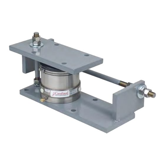
Page 22: Parts Identification H2.5K Load Cell Assembly
PARTS IDENTIFICATION H2.5K Load Cell Assembly 1780-M057-O1 Rev C Hydraulic Floor Stand Tank/Hopper... - Page 23 BASE WELDMENT 1771-B237-08 RETAINER 1771-C202-08 PISTON 1771-C203-08 CYLINDER 1932-B015-08 ROCKER 5930-B106-08 LABEL: CARDINAL LOGO W/WEB ADDRESS 6021-0452 SCW HEX HEAD MACHINE SCW 10-32x.25 SCW UN-BRAKO SOCKET-HD. CAP-SCREW.. 6021-0567 10-32X.750 6021-1130 SCW FLAT HEAD MACHINE SCW 06-32x.250 6031-0521 FITTING, STAINLESS 1/8” PLUG...
-
Page 24: H2.5K Load Cell Stand
PARTS IDENTIFICATION, CONT. H2.5K Load Cell Stand (HBC2.5, Mild Steel and HBCS2.5, Stainless Steel) 1780-M057-O1 Rev C Hydraulic Floor Stand Tank/Hopper... - Page 25 PARTS IDENTIFICATION, CONT. H2.5K Load Cell Stand (HBC2.5, Mild Steel and HBCS2.5, Stainless Steel) 1780-M057-O1 Rev C Hydraulic Floor Stand Tank/Hopper...
- Page 26 PARTS IDENTIFICATION, CONT. H2.5K Load Cell Stand (HBC2.5, Mild Steel) ITEM NO. QTY. PART NUMBER DESCRIPTION 1771-B284-0A BASE PLATE 1771-B286-0A TOP PLATE H2.5K LOAD CELL 1771-B288-08 CHECK ROD HORIZ. 3/8-24UNF X 11 1/2” W/3 1/2” THD BOTH ENDS 6013-0400 NUT HEX 3/8-24 UNF Z/P 6024-0130 WASHER SPHERICAL .406 1771-B287-08...
- Page 27 PARTS IDENTIFICATION, CONT. H2.5K Load Cell Stand (HBCS2.5, Stainless Steel) ITEM NO. QTY. PART NUMBER DESCRIPTION 1771-B284-1A BASE PLATE 1771-B286-1A TOP PLATE H2.5K LOAD CELL 1771-B288-18 CHECK ROD HORIZ. 3/8-24UNF X 11 1/2” W/3 1/2” THD BOTH ENDS 6013-0001 NUT HEX 3/8-24 UNF S.S. 6024-0131 WASHER SPHERICAL .406 S.S.
-
Page 28: H5K Load Cell Assembly
PARTS IDENTIFICATION, CONT. H5K Load Cell Assembly 1780-M057-O1 Rev C Hydraulic Floor Stand Tank/Hopper... - Page 29 RETAINER 1771-B250-08 DIAPHRAGM-H5K 1771-C252-08 PISTON 1771-C253-08 CYLINDER 1932-B015-08 ROCKER 5930-B106-08 LABEL: CARDINAL LOGO W/WEB ADDRESS 6021-0452 SCW HEX HEAD MACHINE SCW 10-32x.25 SCW UN-BRAKO SOCKET-HD. 6021-1111 CAP-SCREW.. .25-28x.750 6021-1130 SCW FLAT HEAD MACHINE SCW 06-32x.250 6031-0521 FITTING, STAINLESS 1/8” PLUG...
-
Page 30: H5K Load Cell Stand
PARTS IDENTIFICATION, CONT. H5K Load Cell Stand (HBC5, Mild Steel and HBCS5, Stainless Steel) 1780-M057-O1 Rev C Hydraulic Floor Stand Tank/Hopper... - Page 31 PARTS IDENTIFICATION, CONT. H5K Load Cell Stand (HBC5, Mild Steel and HBCS5, Stainless Steel) 1780-M057-O1 Rev C Hydraulic Floor Stand Tank/Hopper...
- Page 32 PARTS IDENTIFICATION, CONT. H5K Load Cell Stand (HBC5, Mild Steel) ITEM NO. QTY. PART NUMBER DESCRIPTION 1771-B293-0A BASE PLATE 1771-B294-0A TOP PLATE LOAD CELL 1771-B271-18 CHECK ROD HORIZ. 3/4-16UNF X 23” W/6” THD BOTH ENDS 6013-0188 NUT HEX 3/4-16 UNF Z/P 3501-B107-0A WASHER SPHERICAL .781 1771-B292-18...
- Page 33 PARTS IDENTIFICATION, CONT. H5K Load Cell Stand (HBCS5, Stainless Steel) ITEM NO. QTY. PART NUMBER DESCRIPTION 1771-B293-1A BASE PLATE S.S. 1771-B294-1A TOP PLATE S.S. LOAD CELL 1771-B271-08 CHECK ROD HORIZ. 3/4-16UNF X 23” W/6” THD BOTH ENDS S.S. 6013-0186 NUT HEX 3/4-16 UNF S.S. 3501-B272-0A WASHER SPHERICAL .781 S.S.
-
Page 34: Sst10 Load Cell Assembly
PARTS IDENTIFICATION, CONT. SST10 Load Cell Assembly 1780-M057-O1 Rev C Hydraulic Floor Stand Tank/Hopper... - Page 35 LOAD POST 1771-C143-08 RUBBER BOOT, SST10 1771-D142-0A LOAD CELL WELDMENT FOR SST10 5930-B106-08 LABEL: CARDINAL LOGO W/WEB ADDRESS 6007-0175 BLT HEX HD 3/8-16 X 1/2” NYLON 6028-0104 HOSE CLAMP, 3 5.8 – 6 1/2 6031-0500 CONNECTOR, MALE 1/8” OD – 1/8” MNPT S.S.
-
Page 36: Sst10 Load Cell Stand
PARTS IDENTIFICATION, CONT. SST10 Load Cell Stand (HBC10, Mild Steel and HBCS10, Stainless Steel) 1780-M057-O1 Rev C Hydraulic Floor Stand Tank/Hopper... - Page 37 PARTS IDENTIFICATION, CONT. SST10 Load Cell Stand (HBC10, Mild Steel and HBCS10, Stainless Steel) 1780-M057-O1 Rev C Hydraulic Floor Stand Tank/Hopper...
- Page 38 PARTS IDENTIFICATION, CONT. SST10 Load Cell Stand (HBC10, Mild Steel) ITEM NO. QTY. PART NUMBER DESCRIPTION 1771-B269-1A BASE PLATE 1771-B270-1A TOP PLATE SST10 LOAD CELL 1771-C140-08 LOAD PIN, 5/8” DIA X 4.06 LONG 1771-B214-08 LOAD BUTTON, 1 1/4 DIA 6020-0517 DOWEL PIN, 3/8 DIA X 3/4 LONG 1771-B271-18 CHECK ROD HORIZ.
- Page 39 PARTS IDENTIFICATION, CONT. SST10 Load Cell Stand (HBCS10, Stainless Steel) ITEM NO. QTY. PART NUMBER DESCRIPTION 1771-B269-0A BASE PLATE 1771-B270-0A TOP PLATE SST10 LOAD CELL 1771-C140-08 LOAD PIN, 5/8” DIA X 4.06 LONG 1771-B214-08 LOAD BUTTON, 1 1/4 DIA 17-4 S.S. 6020-0517 DOWEL PIN, 3/8 DIA X 3/4 LONG (S.S.) 1771-B271-08...
-
Page 40: Sst25 Load Cell Assembly
PARTS IDENTIFICATION, CONT. SST25 Load Cell Assembly 1780-M057-O1 Rev C Hydraulic Floor Stand Tank/Hopper... - Page 41 LOAD POST 1771-C163-08 RUBBER BOOT, SST25 1771-D162-0A LOAD CELL WELDMENT FOR SST25 5930-B106-08 LABEL: CARDINAL LOGO W/WEB ADDRESS 6007-0175 BLT HEX HD 3/8-16 X 1/2” NYLON 6028-0104 HOSE CLAMP, 3 5.8 – 6 1/2 6031-0500 CONNECTOR, MALE 1/8” OD – 1/8” MNPT S.S.
-
Page 42: Sst25 Load Cell Stand
PARTS IDENTIFICATION, CONT. SST25 Load Cell Stand (HBC25, Mild Steel and HBCS25, Stainless Steel) 1780-M057-O1 Rev C Hydraulic Floor Stand Tank/Hopper... - Page 43 PARTS IDENTIFICATION, CONT. SST25 Load Cell Stand (HBC25, Mild Steel and HBCS25, Stainless Steel) 1780-M057-O1 Rev C Hydraulic Floor Stand Tank/Hopper...
- Page 44 PARTS IDENTIFICATION, CONT. SST25 Load Cell Stand (HBC25, Mild Steel) ITEM NO. QTY. PART NUMBER DESCRIPTION 1771-B277-1A BASE PLATE 1771-B278-1A TOP PLATE SST25 LOAD CELL 1771-B219-08 LOAD BUTTON, 1 1/4 DIA 17-4 S.S. 6020-0517 DOWEL PIN, 3/8 DIA X 3/4 LONG (S.S.) 1771-B271-18 CHECK ROD HORIZ.
- Page 45 PARTS IDENTIFICATION, CONT. SST25 Load Cell Stand (HBCS25, Stainless Steel) ITEM NO. QTY. PART NUMBER DESCRIPTION 1771-B277-0A BASE PLATE 1771-B278-0A TOP PLATE SST25 LOAD CELL 1771-B219-08 LOAD BUTTON, 1 1/4 DIA 17-4 S.S. 6020-0517 DOWEL PIN, 3/8 DIA X 3/4 LONG (S.S.) 1771-B271-08 CHECK ROD HORIZ.
-
Page 46: Sst50 Load Cell Assembly
PARTS IDENTIFICATION SST50 Load Cell Assembly 1780-M057-O1 Rev C Hydraulic Floor Stand Tank/Hopper... - Page 47 1771-B115-08 RUBBER BOOT 1771-C110-08 LOAD POST 1771-D116-0A LOAD CELL WELDMENT FOR SST50 5930-B106-08 CARDINAL LOGO 6007-0115 BOLT HEX HD 5/8 X 0.5 NYLON 6028-0072 HOSE CLAMP, 1 13/16” – 2 3/4” 6028-0073 HOSE CLAMP, 5 5/8” – 8 1/2” 6031-0500 CONNECTOR, MALE 1/8”...
-
Page 48: Sst50 Load Cell Support Assembly
PARTS IDENTIFICATION, CONT. SST50 Load Cell Support Assembly 1780-M057-O1 Rev C Hydraulic Floor Stand Tank/Hopper... - Page 49 PARTS IDENTIFICATION, CONT. SST50 Load Cell Support Assembly ITEM NO. QTY. PART NUMBER DESCRIPTION 0143-B004 TOP PLATE 1771-B043-08 CLAMP 1771-C094-08 GROUT PLATE 6007-0020 BOLT HEX HD 1/2-13 X 2 3/4” UNC-2A GRADE 5 6007-0159 BLT HEX HD 5/8-11 X 1 1/2”UNC-2A G2 Z/P 6007-0230 BLT HEX HD 5/8-11 X 3”...
-
Page 50: Sst75 Load Cell Assembly
PARTS IDENTIFICATION, CONT. SST75 Load Cell Assembly 1780-M057-O1 Rev C Hydraulic Floor Stand Tank/Hopper... - Page 51 RUBBER BOOT FOR SST75/100 1771-B109-08 LOAD CUP 1771-C110-08 LOAD POST 1771-D040-0A LOAD CELL WELDMENT FOR SST75 5930-B106-08 CARDINAL LOGO 6007-0115 BOLT HEX HD 5/8-11 X 0.5 NYLON 6082-0072 HOSE CLAMP, 1 13/16” – 2 3/4” 6028-0074 HOSE CLAMP, 7 1/8” – 10” 6031-0500...
-
Page 52: Sst75 Load Cell Support Assembly
PARTS IDENTIFICATION, CONT. SST75 Load Cell Support Assembly 1780-M057-O1 Rev C Hydraulic Floor Stand Tank/Hopper... - Page 53 PARTS IDENTIFICATION, CONT. SST75 Load Cell Support Assembly ITEM NO. QTY. PART NUMBER DESCRIPTION 0143-B004 TOP PLATE 1771-B043-08 CLAMP 1771-C042-08 GROUT PLATE 6007-0020 BOLT HEX HD 1/2-13 X 2 3/4” UNC-2A GRADE 5 6007-0159 BLT HEX HD 5/8-11 X 1 1/2”UNC-2A G2 Z/P 6007-0230 BLT HEX HD 5/8-11 X 3”...
-
Page 54: Sst100 Load Cell Assembly
PARTS IDENTIFICATION SST100 Load Cell Assembly 1780-M057-O1 Rev C Hydraulic Floor Stand Tank/Hopper... - Page 55 LOAD CUP 1771-C110-08 LOAD POST 1771-D330-0A LOAD CELL WELDMENT FOR SST100 5930-B106-08 LABEL: CARDINAL LOGO W/WEB ADDRESS 6007-0115 BOLT HEX HD 5/8-11 X 0.5 NYLON 6082-0072 HOSE CLAMP, 1 13/16” – 2 3/4” 6028-0074 HOSE CLAMP, 7 1/8” – 10”...
-
Page 56: Sst100 Load Cell Support Assembly
PARTS IDENTIFICATION, CONT. SST100 Load Cell Support Assembly 1780-M057-O1 Rev C Hydraulic Floor Stand Tank/Hopper... - Page 57 PARTS IDENTIFICATION, CONT. SST100 Load Cell Support Assembly ITEM NO. QTY. PART NUMBER DESCRIPTION 0143-B004 TOP PLATE 1771-B043-08 CLAMP 1771-C042-08 GROUT PLATE 6007-0020 BOLT HEX HD 1/2-13 X 2 3/4” UNC-2A GRADE 5 6007-0159 BLT HEX HD 5/8-11 X 1 1/2”UNC-2A G2 Z/P 6007-0230 BLT HEX HD 5/8-11 X 3”...
-
Page 58: 4-Cell Totalizer Enclosure
PARTS IDENTIFICATION, CONT. 3 & 4 Cell Totalizer Enclosure 6 ± 1/2” 4 CELL ENCLOSURE 3 CELL ENCLOSURE 1780-M057-O1 Rev C Hydraulic Floor Stand Tank/Hopper... - Page 59 PARTS IDENTIFICATION, CONT. 3 & 4 Cell Totalizer Enclosure 1 1/2” 1780-M057-O1 Rev C Hydraulic Floor Stand Tank/Hopper...
- Page 60 PARTS IDENTIFICATION, CONT. 3 & 4 Cell Totalizer Enclosure 8 1/2” 0.281 DIA (TYP) 10” 5” 1780-M057-O1 Rev C Hydraulic Floor Stand Tank/Hopper...
- Page 61 RING TERMINAL, 1/4 STUD 12-10 AWG 3’ 6031-0506 COPPER TUBING 6031-0502 PLUG, BRASS 6021-1707 FHSCS, 1/4-28 X 1/2” 1780-B028-18 LABEL: LOGO & GUARDIAN 1780-B053-0A SHORTER HYD. HOSE (4 CELL SYSTEM) 1780-B053-0A SHORTER HYD. HOSE (3 CELL SYSTEM) 3502-C520-0A TRANS SUPP. BOX 6710-1017 TAPE (AS REQUIRED)
-
Page 62: Cell Output Calibration Worksheet
CELL OUTPUT CALIBRATION WORKSHEET Cell # Dead Load Output - Zero Balance Output = Circuit Gain Cell #1 _______________ - _________________ = __________________ Cell #2 _______________ - _________________ = __________________ Cell #3 _______________ - _________________ = __________________ Cell #4 _______________ - _________________ = __________________ 1780-M057-O1 Rev C ... - Page 63 STATEMENT OF LIMITED WARRANTY WARRANTY TERMS Cardinal Scale Manufacturing Company warrants the equipment we manufacture against defects in material and workmanship. The length and terms and conditions of these warranties vary with the type of product and are summarized below:...
- Page 64 This warranty sets forth the extent of our liability for breach of any warranty or deficiency in connection with the sale or use of our product. Cardinal will not be liable for consequential damages of any nature, including but not limited to loss of profit, delays or expenses, whether based on tort or contract.
- Page 65 1780-M057-O1 Rev C Hydraulic Floor Stand Tank/Hopper...
- Page 66 1780-M057-O1 Rev C Hydraulic Floor Stand Tank/Hopper...
Need help?
Do you have a question about the GUARDIAN and is the answer not in the manual?
Questions and answers