
Related Manuals for EUCHNER CET-AR Series


Summary of Contents for EUCHNER CET-AR Series
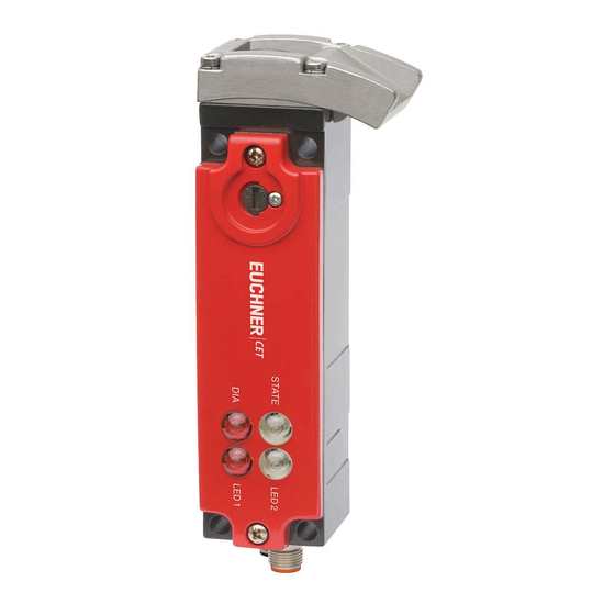
- Page 1 Operating Instructions Transponder-Coded Safety Switch With Guard Locking CET.-AR-… (Unicode/Multicode)
-
Page 2: Table Of Contents
Operating Instructions Transponder-Coded Safety Switch CET.-AR-… Contents About this document ..................... 4 1.1. Scope ............................4 1.2. Target group ..........................4 1.3. Key to symbols ..........................4 1.4. Supplementary documents ......................4 Correct use ......................5 Description of the safety function ................6 Exclusion of liability and warranty ................. 7 General safety precautions ................... - Page 3 Operating Instructions Transponder-Coded Safety Switch CET.-AR-… 10.6. Connector assignment for safety switch CET-AR with plug connectors 2 x M12 .........23 10.6.1. Version without door monitoring output (CET1/2) ............23 10.6.2. Version with door monitoring output (CET3/4) ..............23 10.6.3. Version with door monitoring output (CET3/4) and additional monitoring output OUT on X 2.3 . 10.7.
-
Page 4: About This Document
Important! Always read all documents to gain a complete overview of safe installation, setup and use of the device. The documents can be downloaded from www.euchner.com. For this purpose enter the doc. no. in the search box. (Translation of the original operating instructions) 2110788-13-03/20... -
Page 5: Correct Use
Ì EN 60204-1 The safety switch is allowed to be operated only in conjunction with the intended EUCHNER actuator and the related connec- tion components from EUCHNER. On the use of different actuators or other connection components, EUCHNER provides no warranty for safe function. -
Page 6: Description Of The Safety Function
Operating Instructions Transponder-Coded Safety Switch CET.-AR-… NOTICE For information about combination with an AR evaluation unit, please refer to chapter 10.11. Information on operation on an AR evaluation unit on page 35. 3. Description of the safety function Devices from this series feature the following safety functions: Monitoring of guard locking and the position of the guard (interlocking device with guard locking according to EN ISO 14119) Ì... -
Page 7: Exclusion Of Liability And Warranty
Operating Instructions Transponder-Coded Safety Switch CET.-AR-… Control of guard locking If the device is used as guard locking for personnel protection, the control of the guard locking must be regarded as a safety function. The device does not feature a safety characteristic for the control of the guard locking, because the guard locking solenoid is completely disconnected from outside the device (no control function within the device). -
Page 8: General Safety Precautions
Prior to use, read the operating instructions and keep these in a safe place. Ensure the operating instructions are always available during mounting, setup and servicing. For this reason you should archive a printed copy of the operating instructions. You can download the operating instructions from www.euchner.com. (Translation of the original operating instructions) 2110788-13-03/20... -
Page 9: Function
Operating Instructions Transponder-Coded Safety Switch CET.-AR-… 6. Function The device permits the locking of movable guards. The system consists of the following components: coded actuator (transponder) and switch. Ramp/switch head Whether the device learns the complete actuator code (unicode) or not (multicode) depends on the respective version. -
Page 10: Door Monitoring Output (Out D)
Operating Instructions Transponder-Coded Safety Switch CET.-AR-… 6.3. Door monitoring output (OUT D) Versions CET3 and CET4 feature a door monitoring output (OUT D). The door monitoring output is switched on as soon as the actuator is above the extended plunger (state: guard closed and not locked). The door monitoring output also remains switched on when guard locking is active. -
Page 11: Switching States
Operating Instructions Transponder-Coded Safety Switch CET.-AR-… 6.8. Switching states The detailed switching states for your switch can be found in the system status table. All safety outputs, monitoring outputs and LED displays are described there. Guard closed and locked Guard closed and not locked Guard open Voltage at guard locking solenoid (irrelevant) -
Page 12: Manual Release
Operating Instructions Transponder-Coded Safety Switch CET.-AR-… 7. Manual release Some situations require the guard locking to be released manually (e.g. malfunctions or an emergency). A function test should be performed after release. More information on this topic can be found in the standard EN ISO 14119:2013, section 5.7.5.1. The device can feature the following release functions: 7.1. -
Page 13: Emergency Release (Can Be Retrofitted)
Operating Instructions Transponder-Coded Safety Switch CET.-AR-… 7.2. Emergency release (can be retrofitted) Permits opening of a locked guard from outside the danger zone without tools. For mounting, see the mounting supplement. The safety outputs are switched off when the emergency release is actuated. Use the safety outputs to generate a stop command The monitoring output OUT is switched off;... -
Page 14: Escape Release (Optional)
Operating Instructions Transponder-Coded Safety Switch CET.-AR-… 7.3. Escape release (optional) Permits opening of a locked guard from the danger zone without tools (see chapter 13.2. Di‑ mension drawing for safety switch CET.‑AR‑… on page 44). The safety outputs are switched off when the escape release is actuated. Use the safety outputs to generate a stop command The monitoring output OUT is switched off;... -
Page 15: Wire Front Release (Optional)
Operating Instructions Transponder-Coded Safety Switch CET.-AR-… 7.4. Wire front release (optional) Release via a pull wire. Depending on the type of attachment, the wire front release can be used as emergency release or escape release. The following applies to non-latching wire front releases: If the release is to be used as an emergency release, one of the following measures must be taken (see EN ISO 14119:2013, section 5.7.5.3): Ì... -
Page 16: Mounting
Ensure that the actuator contacts the ramp in the designated area (see figure below). Marks on the ramp specify the prescribed approach zone. Tip! EUCHNER offers special cover plates to improve protection against tampering. These accessories can be found at www.euchner.com. Figure 2:... - Page 17 Operating Instructions Transponder-Coded Safety Switch CET.-AR-… Note the following points: Actuator and safety switch must be fitted so that Ì the active faces of the actuator and the safety switch are parallel with each other. Ì the actuator is fully inserted into the switch recess when the guard is closed. Ì...
-
Page 18: Electrical Connection
10. Electrical connection The following connection options are available: Ì Separate operation Ì Series connection with Y-distributors from EUCHNER (only with M12 plug connectors) Ì Series connection, e.g. with wiring in the control cabinet Ì Operation on an AR evaluation unit WARNING In the event of a fault, loss of the safety function due to incorrect connection. -
Page 19: Notes About
Operating Instructions Transponder-Coded Safety Switch CET.-AR-… 10.1. Notes about Important! Ì This device is intended to be used with a Class 2 power source in accordance with UL1310. As an alternative an LV/C (Limited Voltage/Current) power source with the following properties can be used: - This device shall be used with a suitable isolating source in conjunction with a fuse in accordance with UL248. -
Page 20: Requirements For Connecting Cables
Ì On the use of other connection components, the requirements in the following table apply. EUCHNER provides no warranty for safe function in case of failure to comply with these require- ments. Observe the following requirements with respect to the connecting cables:... -
Page 21: Maximum Cable Lengths
Operating Instructions Transponder-Coded Safety Switch CET.-AR-… 10.5. Maximum cable lengths Switch chains are permitted up to a maximum overall cable length of 200 m taking into account the voltage drop as a result of the cable resistance (see table below with example data and case example). =200 m = 24 V -20% = 24 V -10%... -
Page 22: Determining Cable Lengths Using The Example Table
Operating Instructions Transponder-Coded Safety Switch CET.-AR-… 10.5.1. Determining cable lengths using the example table Example: Six switches are to be used in series. Cabling with a length of 40 m is routed from a safety relay in the control cabinet to the last switch (#6). Cables with a length of 20 m each are connected between the individual CES-AR/CET-AR safety switches. -
Page 23: Connector Assignment For Safety Switch Cet-Ar With Plug Connectors 2 X M12
This connection must be connected to 0 V. Version without feedback loop and without teach-in input: This connection must be connected to 0 V. 1) Only for standard EUCHNER connecting cable. 2) With dual-channel solenoid control, do not connect to 0 V U 3) Only for ID no. 109015 10.6.2. -
Page 24: Version With Door Monitoring Output (Cet3/4) And Additional Monitoring Output Out On
Operating voltage of guard locking solenoid, 24 V DC (indication on X 2.4 LED 1) X 2.5 n.c. 1) Only for standard EUCHNER connecting cable. 10.7. Connector assignment for safety switch CET-AR with plug connector M23 (RC18) 10.7.1. Version without door monitoring output (CET1/2) Wiring diagram D... -
Page 25: Version With Door Monitoring Output (Cet3/4)
0 V U Operating voltage of guard locking solenoid, 0 V 0 V U Operating voltage of AR electronics, 0 V 1) Only for standard EUCHNER connecting cable. 2) With dual-channel solenoid control, do not connect to 0 V U 2110788-13-03/20 (Translation of the original operating instructions) -
Page 26: Connector Assignment Of Y-Distributor
Operating Instructions Transponder-Coded Safety Switch CET.-AR-… 10.8. Connector assignment of Y-distributor (Only for version with plug connectors 2 x M12) Connector assignment for safety switch CET-AR (plug X1, 8-pin plug) and Y-distributor (8-pin socket) Function X1.1 X1.2 X1.3 X1.4 X1.5 OUT/DIA X1.6 X1.7... -
Page 27: Connection Of A Single Cet-Ar
The user is responsible for safe inte- gration into the overall system. Detailed application examples can be found at www.euchner.com. Simply enter the order number of your switch in the search box. You will find all available connec- tion examples for the device in Downloads. - Page 28 Operating Instructions Transponder-Coded Safety Switch CET.-AR-… 24V DC 24V DC LED1 LED2 X2:4 X2:5 X2:2 X2:3 X1:2 X1:8 X1:6 X1:1 Safety Inputs Read Head Monitoring Output Safety Outputs X2:1 X1:7 X1:5 X1:3 X1:4 0V(UCM) 0V(UB) Connected load Figure 4: Wiring diagram A, CET 1/2-AR with plug connectors 2 x M12 Single-channel control of the guard locking solenoid 24V DC 24V DC...
- Page 29 Operating Instructions Transponder-Coded Safety Switch CET.-AR-… 24V DC 24V DC LED1 X2:4 X2:5 X2:3 X1:2 X1:8 X1:6 X1:1 Safety Inputs Read Head Door Monitoring Monitoring Output Safety Outputs X2:1 X1:7 X2:2 X1:5 X1:3 X1:4 0V(UCM) 0V(UB) OUTD Connected load Figure 6: Wiring diagram B, CET 3/4-AR with plug connectors 2 x M12 Single-channel control of the guard locking solenoid 24V DC...
- Page 30 Operating Instructions Transponder-Coded Safety Switch CET.-AR-… 24V DC 24V DC X2:4 X1:2 X1:8 X1:6 X1:1 Safety Inputs Read Head Door Monitoring Monitoring Output Safety Outputs X2:5 X2:1 X2:3 X1:7 X2:2 X1:5 X1:3 X1:4 0V(UCM) 0V(UB) OUTD Connected load Figure 8: Wiring diagram C, CET 3/4-AR with plug connectors 2 x M12 an additional monitoring output OUT Single-channel control of the guard locking solenoid 24V DC...
- Page 31 Operating Instructions Transponder-Coded Safety Switch CET.-AR-… 24V DC 24V DC LED1 LED2 Safety Inputs Read Head Monitoring Output Safety Outputs 0V(UCM) 0V(UB) Connected load Figure 10: Wiring diagram D, CET 1/2-AR with plug connector M23 Single-channel control of the guard locking solenoid 24V DC 24V DC LED1...
- Page 32 Operating Instructions Transponder-Coded Safety Switch CET.-AR-… 24V DC 24V DC LED1 LED2 Safety Inputs Read Head Monitoring Outputs Door Monitoring Safety Outputs monitoring Output 0V(UCM) 0V(UB) OUTD Connected load Figure 12: Wiring diagram E, CET 3/4-AR with plug connector M23, versions with and without teach-in input Single-channel control of the guard locking solenoid 24V DC 24V DC...
-
Page 33: Connection Of Several Cet-Ar In A Switch Chain
The user is responsible for safe inte- gration into the overall system. Detailed application examples can be found at www.euchner.com. Simply enter the order number of your switch in the search box. You will find all available connec- tion examples for the device in Downloads. - Page 34 Operating Instructions Transponder-Coded Safety Switch CET.-AR-… Figure 14: Connection example for operation in a CES-AR switch chain (Translation of the original operating instructions) 2110788-13-03/20...
-
Page 35: Information On Operation On An Ar Evaluation Unit
- CET 3/4-AR from version V1.7.0: The device tolerates switch-on and shut-off pulses up to 5 ms. Ì Always connect inputs IA and IB directly to a power supply unit or to outputs OA and OB of another EUCHNER AR device (series connection). Pulsed signals must not be present at inputs IA and IB. - Page 36 Operating Instructions Transponder-Coded Safety Switch CET.-AR-… Figure 15: Connection example for mixed series connection (2 x CES and 1 x CET) to ET200 (Translation of the original operating instructions) 2110788-13-03/20...
-
Page 37: Setup
OUT D is switched on (door is closed) Ì Depending on version, the function of LED 1 and LED 2 can differ. Detailed information is available on the enclosed data sheet or at www.euchner.com. Simply enter the order number of your device in the search box. 11.2. -
Page 38: Preparing Device For The Teach-In Operation And Teaching-In Actuator
Operating Instructions Transponder-Coded Safety Switch CET.-AR-… 11.2.1. Preparing device for the teach-in operation and teaching-in actuator 1. Connect the switch as shown below, but do not apply any voltage to U yet. For version with teach-in input: For the teach-in standby state, the teach-in input J must be connected to +24 V DC. For devices without teach-in input: The circuit is the same, but connection J is omitted. -
Page 39: Teach-In Function With Series Connection, Replacing And Teaching In Device
Operating Instructions Transponder-Coded Safety Switch CET.-AR-… 11.2.2. Teach-in function with series connection, replacing and teaching in device It is recommended not to teach-in the actuators in the series connection but to teach them in one by one instead. Teach-in in a series connection works analogously to separate operation in principle. All switches in the chain can be taught-in at the same time. -
Page 40: Functional Check
Operating Instructions Transponder-Coded Safety Switch CET.-AR-… 11.3. Functional check WARNING Danger of fatal injury as a result of faults in installation and functional check. Ì Before carrying out the functional check, make sure that there are no persons in the danger zone. Ì... -
Page 41: System Status Table
Operating Instructions Transponder-Coded Safety Switch CET.-AR-… 12. System status table LED indicator Output Operating mode State 10 Hz Self-test Self-test after power-up (10 s) closed Normal operation, door closed and locked Normal operation, door closed and locked, safety outputs not switched because: 1 x in- closed - Preceding device in the switch chain signals door open (only with series... -
Page 42: Technical Data
Operating Instructions Transponder-Coded Safety Switch CET.-AR-… 13. Technical data NOTICE If a product data sheet is included with the product, the information on the data sheet applies in case of discrepancies with the operating instructions. 13.1. Technical data for safety switch CET.-AR-… Parameter Value Unit... -
Page 43: Typical System Times
Operating Instructions Transponder-Coded Safety Switch CET.-AR-… 13.1.1. Typical system times Please refer to the technical data for the exact values. Ready delay: After switch-on, the device carries out a self-test. The system is ready for operation only after this time. Turn-on time of safety outputs: The max. -
Page 44: Dimension Drawing For Safety Switch Cet.-Ar
Operating Instructions Transponder-Coded Safety Switch CET.-AR-… 13.2. Dimension drawing for safety switch CET.-AR-… Version with plug connectors 2 x M12 With escape release LED 2 LED 1 Basic position for escape release STATE Release by pressing Auxiliary release 43,6 67,2 CET.-AR...CRA... - Page 45 Operating Instructions Transponder-Coded Safety Switch CET.-AR-… Version with plug connector M23 (RC18) Dimensions with plug connector M23 Cable outlet left Cable outlet right M23x1 21,5 Versions with manual release options With auxiliary key release With emergency release With wire front release 16,7 L = 19 or 71 mm (depending on version)
-
Page 46: Technical Data For Actuator Cet-A-B
Operating Instructions Transponder-Coded Safety Switch CET.-AR-… 13.3. Technical data for actuator CET-A-B… Parameter Value Unit min. typ. max. Housing material Stainless steel Stroke, max. Weight 0.25 Ambient temperature - 20 + 55 °C Degree of protection IP67 (transponder protection) Mechanical life 1 x 10 operating cycles Locking force, max. -
Page 47: Ordering Information And Accessories
14. Ordering information and accessories Tip! Suitable accessories, e.g. cables or assembly material, can be found at www.euchner.com. To order, enter the order number of your item in the search box and open the item view. Accessories that can be combined with the item are listed in Accessories. -
Page 48: Declaration Of Conformity
Operating Instructions Transponder-Coded Safety Switch CET.-AR-… 17. Declaration of conformity (Translation of the original operating instructions) 2110788-13-03/20... - Page 49 Operating Instructions Transponder-Coded Safety Switch CET.-AR-… 2110788-13-03/20 (Translation of the original operating instructions)
- Page 50 Operating Instructions Transponder-Coded Safety Switch CET.-AR-… (Translation of the original operating instructions) 2110788-13-03/20...
- Page 51 Operating Instructions Transponder-Coded Safety Switch CET.-AR-… 2110788-13-03/20 (Translation of the original operating instructions)
- Page 52 Operating Instructions Transponder-Coded Safety Switch CET.-AR-… (Translation of the original operating instructions) Copyright: © EUCHNER GmbH + Co. KG, 03/2020 Subject to technical modifications; no responsibility is accept- ed for the accuracy of this information. Third-party trademark information: SIMATIC ET200pro and ET200S are trademarks of SIEMENS...
Need help?
Do you have a question about the CET-AR Series and is the answer not in the manual?
Questions and answers