
Related Manuals for EUCHNER CET.-AP Series


Summary of Contents for EUCHNER CET.-AP Series
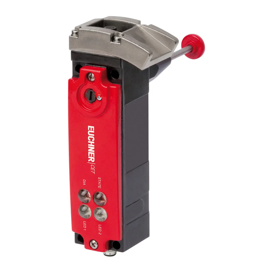
- Page 1 Operating Instructions Transponder-Coded Safety Switch With Guard Locking CET.-AP-… (Unicode/Multicode)
-
Page 2: Table Of Contents
Operating Instructions Transponder-Coded Safety Switch CET.-AP-… Contents About this document ..................... 4 1.1. Scope ............................4 1.2. Target group ..........................4 1.3. Key to symbols ..........................4 1.4. Supplementary documents ......................4 Correct use ......................5 Description of the safety function ................6 Exclusion of liability and warranty ................. 6 General safety precautions ................... - Page 3 Operating Instructions Transponder-Coded Safety Switch CET.-AP-… 10.6. Connector assignment of safety switch CET-AP for connection to decentralized peripheral systems with plug connectors 2 x M12 (5-pin; pin 5 not used) and additional door monitoring output OUT D on X2.2 ............................19 10.7. Connector assignment of safety switch CET-AP with plug connector 1 x M12 (8-pin) ......19 10.8.
-
Page 4: About This Document
Important! Always read all documents to gain a complete overview of safe installation, setup and use of the device. The documents can be downloaded from www.euchner.com. For this purpose enter the doc. no. in the search box. (Translation of the original operating instructions) 2122242-04-05/18... -
Page 5: Correct Use
EN 60204-1, Safety of machinery – Electrical equipment of machines – Part 1: General requirements The safety switch is allowed to be operated only in conjunction with the intended EUCHNER actuator and the related connec- tion components from EUCHNER. On the use of different actuators or other connection components, EUCHNER provides no warranty for safe function. -
Page 6: Description Of The Safety Function
Operating Instructions Transponder-Coded Safety Switch CET.-AP-… 3. Description of the safety function Devices from this series feature the following safety functions: Monitoring of guard locking and the position of the guard (interlocking device with guard locking according to EN ISO 14119) Ì Safety function (see chapter 6.8. -
Page 7: General Safety Precautions
Prior to use, read the operating instructions and keep these in a safe place. Ensure the operating instructions are always available during mounting, setup and servicing. EUCHNER cannot provide any warranty in relation to the readability of the CD for the storage period required. For this reason you should archive a printed copy of the operating instructions. -
Page 8: Function
Operating Instructions Transponder-Coded Safety Switch CET.-AP-… 6. Function The device permits the locking of movable guards. The system consists of the following components: coded actuator (transponder) and switch. Ramp/switch head Whether the device learns the complete actuator code (unicode) or not (multicode) depends on the respective version. -
Page 9: Door Monitoring Output (Out D)
Operating Instructions Transponder-Coded Safety Switch CET.-AP-… 6.3. Door monitoring output (OUT D) Versions CET3 and CET4 feature a door monitoring output (OUT D). The door monitoring output is switched on as soon as the actuator is above the extended plunger (state: guard closed and not locked). The door monitoring output also remains switched on when guard locking is active. -
Page 10: Start Button And Feedback Loop (Optional)
Operating Instructions Transponder-Coded Safety Switch CET.-AP-… 6.7. Start button and feedback loop (optional) A start button and a feedback loop can be connected (for monitoring downstream relays and contactors) (input Y). Important! Faults on the start button/in the feedback loop are not detected. This can lead to unintentional auto- matic starting. -
Page 11: Manual Release
Operating Instructions Transponder-Coded Safety Switch CET.-AP-… 7. Manual release Some situations require the guard locking to be released manually (e.g. malfunctions or an emergency). A function test should be performed after release. More information on this topic can be found in the standard EN ISO 14119:2013, section 5.7.5.1. The device can feature the following release functions: 7.1. -
Page 12: Emergency Unlocking (Can Be Retrofitted)
Operating Instructions Transponder-Coded Safety Switch CET.-AP-… 7.2. Emergency unlocking (can be retrofitted) Permits opening of a locked guard from outside the danger zone without tools. For mounting, see the mounting supplement. Important! Ì It must be possible to operate the emergency unlocking manually from outside the protected area without tools. -
Page 13: Wire Front Release (Optional)
Operating Instructions Transponder-Coded Safety Switch CET.-AP-… 7.4. Wire front release (optional) Release via a pull wire. Depending on the type of attachment, the wire front release can be used as emergency unlocking or escape release. The following applies to non-latching wire front releases. If the release is to be used as emergency unlocking, one of the following measures must be taken (see EN ISO 14119:2013, section 5.7.5.3): Ì... -
Page 14: Mounting
Ensure that the actuator contacts the ramp in the designated area (see figure below). Marks on the ramp specify the prescribed approach zone. Tip! EUCHNER offers special cover plates to improve protection against tampering. These accessories can be found at www.euchner.com. Figure 2:... - Page 15 Operating Instructions Transponder-Coded Safety Switch CET.-AP-… Note the following points: Actuator and safety switch must be fitted so that Ì the active faces of the actuator and the safety switch are parallel with each other. Ì the actuator is fully inserted into the switch recess when the guard is closed. Ì...
-
Page 16: Electrical Connection
Operating Instructions Transponder-Coded Safety Switch CET.-AP-… 10. Electrical connection WARNING If there is a mistake, loss of the safety function due to incorrect connection. Ì To ensure safety, both safety outputs (OA and OB) must always be evaluated. Ì Monitoring outputs must not be used as safety outputs. Ì... -
Page 17: Notes About
Operating Instructions Transponder-Coded Safety Switch CET.-AP-… 10.1. Notes about Important! Ì For use and operation as per the requirements*, a power supply with the feature “for use in class 2 circuits” must be used. The same requirement applies to the safety outputs. Alternative solutions must comply with the following requirements: - Electrically isolated power supply unit in combination with fuse as per UL248. -
Page 18: Requirements For Connection Cables
Ì On the usage of other connection components, the requirements in the following table apply. EUCHNER provides no warranty for safe function in case of failure to comply with these require- ments. Observe the following requirements with respect to the connection cables:... -
Page 19: Connector Assignment Of Safety Switch Cet-Ap For Connection To Decentralized Peripheral Systems With Plug Connectors 2 X M12 (5-Pin; Pin 5 Not Used) Without Door Monitoring Output
Operating voltage of guard locking solenoid 24 V DC X2.3 X 2.5 n.c. 1) Only for standard EUCHNER connection cable 10.6. Connector assignment of safety switch CET-AP for connection to decentralized peripheral systems with plug connectors 2 x M12 (5-pin; pin 5 not used) and additional door monitoring output OUT D on X2.2... -
Page 20: Connector Assignment Of Safety Switch Cet-Ap With Plug Connector M23 (Rc18)
YEGN Teach-in input n.c. Do not connect to 0 V! n.c. BNGN n.c. YEBN n.c. 0V U 0 V solenoid 0 V U Operating voltage, 0 V 1) Only for standard EUCHNER connection cable (Translation of the original operating instructions) 2122242-04-05/18... -
Page 21: Connection
The user is responsible for safe inte- gration into the overall system. Detailed application examples can be found at www.euchner.com. Simply enter the order number in the search box. All available connection examples for the device can be found in “Downloads.”... -
Page 22: Notes On Operation With Safe Control Systems
A detailed example of connecting and setting the parameters of the control system is available for many devices at www.euchner.com in the area Download » Applications » CET. The features of the respective device are dealt with there in greater detail. -
Page 23: Setup
- LED2: green = OUT D is switched on (door is closed) Ì Depending on version, the function of LED 1 and LED 2 can differ. Detailed information is available on the enclosed data sheet or at www.euchner.com. Simply enter the order number in the search box. 11.2. -
Page 24: Preparing Device For The Teach-In Operation And Teaching In Actuator
Operating Instructions Transponder-Coded Safety Switch CET.-AP-… 11.2.1. Preparing device for the teach-in operation and teaching in actuator 1. Connect the switch as shown below, but do not apply any voltage to U yet. In case of version with teach-in input: For the teach-in standby state, the teach-in input J must be connected to +24 V DC. -
Page 25: Functional Check
Operating Instructions Transponder-Coded Safety Switch CET.-AP-… 11.3. Functional check WARNING Danger of fatal injury as a result of faults in installation and functional check. Ì Before carrying out the functional check, make sure that there are no persons in the danger zone. Ì... -
Page 26: System Status Table
Operating Instructions Transponder-Coded Safety Switch CET.-AP-… 12. System status table LED indicator Output Operating mode State closed Normal operation, door closed and locked Normal operation, door closed and locked, safety outputs not switched 1 x in- closed because: verse - Feedback loop not closed (if fitted) Normal operation Normal operation, door closed and not locked closed... -
Page 27: Technical Data
Operating Instructions Transponder-Coded Safety Switch CET.-AP-… 13. Technical data NOTICE If a data sheet is included with the product, the information on the data sheet applies. 13.1. Technical data for safety switch CET.-AP-C..-AH-… Value Unit Parameter min. typ. max. General Material, ramp Stainless steel Material, safety switch housing... -
Page 28: Typical System Times
Operating Instructions Transponder-Coded Safety Switch CET.-AP-… 13.1.1. Typical system times Please refer to the technical data for the exact values. Ready delay: After switching on, the device carries out a self-test. The system is ready for operation only after this time. Switch-on time of safety outputs: The max. -
Page 29: Dimension Drawing For Safety Switch Cet.-Ap
Operating Instructions Transponder-Coded Safety Switch CET.-AP-… 13.2. Dimension drawing for safety switch CET.-AP-… Version with plug connectors 2 x M12 With escape release LED 2 LED 1 Basic position for escape release STATE Release by pressing Auxiliary release 43,6 67,2 CET.-AR...CRA... 91,2 CET.-AR...CDA... ∅ 6.5 For M6 screw DIN 1207/ISO 4762 With angle connectors... - Page 30 Operating Instructions Transponder-Coded Safety Switch CET.-AP-… Version with plug connector M23 (RC18) Dimensions with plug connector M23 Cable exit left Cable exit right M23x1 21,5 With auxiliary key release With emergency unlocking With wire front release 16,7 (Translation of the original operating instructions) 2122242-04-05/18...
-
Page 31: Technical Data For Actuator Cet-A-B
Operating Instructions Transponder-Coded Safety Switch CET.-AP-… 13.3. Technical data for actuator CET-A-B… Parameter Value Unit min. typ. max. Housing material Stainless steel Stroke, max. Weight 0.25 Ambient temperature - 20 + 55 °C Degree of protection IP 67 Mechanical life 1 x 10 operating cycles Locking force, max. -
Page 32: Ordering Information And Accessories
14. Ordering information and accessories Tip! Suitable accessories, e.g. cables or assembly material, can be found at www.euchner.com. To order, enter the order number of your item in the search box and open the item view. Accessories that can be combined with the item are listed in “Accessories.”... -
Page 33: Declaration Of Conformity
Operating Instructions Transponder-Coded Safety Switch CET.-AP-… 17. Declaration of conformity 2122242-04-05/18 (Translation of the original operating instructions) - Page 34 Operating Instructions Transponder-Coded Safety Switch CET.-AP-… (Translation of the original operating instructions) 2122242-04-05/18...
- Page 35 Operating Instructions Transponder-Coded Safety Switch CET.-AP-… 2122242-04-05/18 (Translation of the original operating instructions)
- Page 36 Operating Instructions Transponder-Coded Safety Switch CET.-AP-… (Translation of the original operating instructions) Copyright: © EUCHNER GmbH + Co. KG, 05/2018 Subject to technical modifications; no responsibility is accept- ed for the accuracy of this information. Third-party trademark information: SIMATIC ET200pro and ET200S are trademarks of SIEMENS...
Need help?
Do you have a question about the CET.-AP Series and is the answer not in the manual?
Questions and answers