Ingersoll-Rand 100PQ1 Maintenance Information
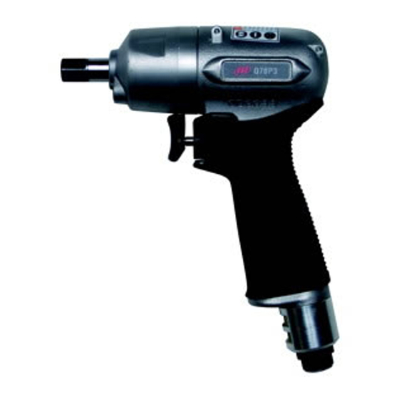
Air impulse wrench (twin blade)
Hide thumbs
Also See for 100PQ1:
- Operation and maintenance manual (28 pages) ,
- Product information (57 pages)

Subscribe to Our Youtube Channel
Related Manuals for Ingersoll-Rand 100PQ1


Summary of Contents for Ingersoll-Rand 100PQ1
- Page 1 47109525 Edition 1 September 2010 Air Impulse Wrench (Twin Blade) Models 100PQ1 and 100PQ1–EU Maintenance Information Save These Instructions...
- Page 2 WARNING Always wear eye protection when operating or performing maintenance on this tool. Always turn off the air supply and disconnect the air supply hose before installing, removing or adjusting any accessory on this tool or before performing any maintenance on this tool. Note: When reading the instructions, refer to exploded diagrams in Parts Information Manual when applicable (see under Related Documentation for form numbers).
- Page 3 Disassembly General Instructions 1. Do not disassemble the tool any further than necessary to replace Pressing Tap edge lightly with or repair damaged parts. Sleeve brass hammer or use 2. When grasping a tool or part in a vise, always use leather–covered pressing sleeve from or copper–covered vise jaws to protect the surface of the part tool kit...
- Page 4 4. Remove the motor from the vise jaws and remove the Front End Plate (27), Front End Plate Bearing (29), Cylinder Assembly (25) and Vanes (26) from the Rotor. 5. Remove the Rear Motor Seal (17) from the Motor Housing. 6.
- Page 5 13. Using an arbor press and a piece of tubing that contacts the outer Counterclockwise to tighten ring of the bearings, press the Front End Plate Bearing (29) into the Front End Plate (27) and the Rear End Plate Bearing (22) into the Rear End Plate (21).
- Page 6 10. Install the Adjustment Bolt Seal (35) followed by the Seal Washer 12. Install the Oil Plug (32) and Oil Plug Seal (33) in the liner housing (35A) and Seal Back–up Ring (36) on the Torque Adjustment Bolt hole 180 degrees from the Torque Adjustment Bolt. and thread the assembled Bolt into the Liner Housing.
- Page 7 Notes:...
- Page 8 www.ingersollrandproducts.com © 2010 Ingersoll Rand...
Need help?
Do you have a question about the 100PQ1 and is the answer not in the manual?
Questions and answers