
Related Manuals for National Instruments SC-2043-SG


Summary of Contents for National Instruments SC-2043-SG
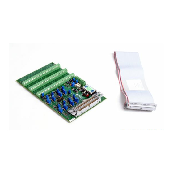
- Page 1 SC-2043-SG User Manual Eight-Channel Strain Gauge Signal Conditioning Accessory August 1996 Edition Part Number 371201A-01 © Copyright 1995, 1996 National Instruments Corporation. All Rights Reserved.
- Page 2 National Instruments Corporate Headquarters 6504 Bridge Point Parkway Austin, TX 78730-5039 (512) 794-0100 Technical support fax: (800) 328-2203 (512) 794-5678 Branch Offices: Australia 03 9 879 9422, Austria 0662 45 79 90 0, Belgium 02 757 00 20, Canada (Ontario) 519 622 9310, Canada (Québec) 514 694 8521, Denmark 45 76 26 00, Finland 90 527 2321, France 1 48 14 24 24,...
- Page 3 Limited Warranty The SC-2043-SG is warranted against defects in materials and workmanship for a period of one year from the date of shipment, as evidenced by receipts or other documentation. National Instruments will, at its option, repair or replace equipment that proves to be defective during the warranty period. This warranty includes parts and labor.
- Page 4 Any use or application of National Instruments products for or involving medical or clinical treatment must be performed by properly trained and qualified medical personnel, and all traditional medical safeguards, equipment, and procedures that are appropriate in the particular situation to prevent serious injury or death should always continue to be used when National Instruments products are being used.
-
Page 5: Table Of Contents
Signal Connections ......................3 I/O Connector Pin Description..................3-1 Screw Terminal Description ..................3-6 Analog Input Connections ................. 3-7 Sensor Connection to the SC-2043-SG..........3-7 Full-Bridge Connection.............. 3-8 Half-Bridge Connection ............. 3-8 Quarter-Bridge Connection ............3-9 Offset Nulling ........................ 3-9 Offset Nulling Adjustment ................. - Page 6 Calibration Procedures ..................... 5-1 Excitation Adjustment....................5-1 Onboard Excitation Source ................5-1 External Excitation Source................. 5-2 Appendix A Specifications ........................A-1 Appendix B Customer Communication ....................B-1 Glossary ..........................G-1 Index ............................I-1 SC-2043-SG User Manual © National Instruments Corporation...
- Page 7 Figure 3-3. Quarter-Bridge Connection to the SC-2043-SG ..........3-9 Figure 4-1. SC-2043-SG Block Diagram ................4-2 Tables Table 2-1. Installation and Cabling Options for the SC-2043-SG ........2-1 Table 2-2. Power Supply Selection ..................2-3 Table 2-3. Onboard/External Excitation Jumpers ..............2-4 Table 2-4.
-
Page 8: About This Manual
DAQ board via a 50-pin connector. The SC-2043-SG also has breakout screw terminals for additional analog inputs (MIO and MIO E Series boards only), analog outputs, and digital and timing I/O pins on the DAQ board I/O connector. -
Page 9: Conventions Used In This Manual
Glossary. National Instruments Documentation The SC-2043-SG User Manual is one piece of the documentation set for your system. You could have any of several types of manuals, depending on the hardware and software in your system. Use the manuals you have as follows: •... -
Page 10: Related Documentation
Your DAQ hardware user manual Customer Communication National Instruments wants to receive your comments on our products and manuals. We are interested in the applications you develop with our products, and we want to help if you have problems with them. To make it easy for you to contact us, this manual contains comment and configuration forms for you to complete. -
Page 11: Chapter 1 Introduction
I/O lines on the DAQ board interfacing connector. The SC-2043-SG is a circuitboard assembly that is placed on a workbench or mounted in a 19-in. rack. The SC-2043-SG draws power from the DAQ board via the 50-pin interfacing connector. -
Page 12: Software Programming Choices
NI-DAQ Driver Software The NI-DAQ driver software is included at no charge with all National Instruments DAQ hardware. NI-DAQ is not packaged with SCXI or accessory products, except for the SCXI-1200. NI-DAQ has an extensive library of functions that you can call from your application programming environment. -
Page 13: Register-Level Programming
Figure 1-1. The Relationship between the Programming Environment, NI-DAQ, and Your Hardware Register-Level Programming The final option for programming any National Instruments DAQ hardware is to write register- level software. Writing register-level programming software can be very time-consuming and inefficient and is not recommended for most users. -
Page 14: Unpacking
Chapter 1 Unpacking Your SC-2043-SG board is shipped in an antistatic package to prevent electrostatic damage to the board. Electrostatic discharge can damage several components on the board. To avoid such damage in handling the board, take the following precautions: •... -
Page 15: Installation And Configuration
Lab/1200 (J9) 1 To install the SC-2043-SG with any of these boards, refer to the installation guide of the cable kit for instructions. 2 The NB-MIO-16H and AT-MIO-16H boards have a maximum gain of 8 and are not intended for interfacing to low-level signals. -
Page 16: Figure 2-1. Sc-2043-Sg Parts Locator Diagram
Installation and Configuration Chapter 2 The SC-2043-SG has one slide switch and 12 jumpers that you use to configure your board. Figure 2-1 shows the switch and jumpers in the parts locator diagram. Screen Printed Screw Product Name and Terminal Label... -
Page 17: Power Supply Selection
SW1 to the EXT position to draw power from an external +5 V power supply connected to J8. In external power mode, the SC-2043-SG has two fuses, F1 and F2, to limit the current to 1 A at +5 V. The board also has a spare fuse (F3), as shown in Figure 2-1. -
Page 18: Onboard/External Excitation Selection
(factory setting) EXT position—Place jumpers W1 W1, W3 and W3 in this position to provide excitation voltage from an external excitation source connected to connector J7. SC-2043-SG User Manual © National Instruments Corporation... -
Page 19: Local Excitation Sense Selection
MIO or MIO E Series Boards If you are using the SC-2043-SG with an MIO or MIO E Series board, you can locally sense the exact level of the excitation voltage by routing the excitation voltage (internal or external) to one of two analog channels, selected by jumpers W8 and W2. -
Page 20: Lab/1200 Series Boards
Chapter 2 Lab/1200 Series Boards If you are using the SC-2043-SG with a Lab/1200 Series board, you can locally sense the exact level of the excitation voltage by routing the excitation voltage (internal or external) to ACH0, configured by jumper W2. The SC-2043-SG also has jumper W8, which you must also configure. -
Page 21: Bridge Completion Selection
Jumpers W4–W7 and W10–W13 select half-bridge or full-bridge configuration for each channel on the SC-2043-SG. Setting a jumper in the FB position disconnects the half-bridge completion network from the channel and connects the CHn- screw terminal to the negative input of the instrumentation amplifier for full-bridge signal inputs. -
Page 22: Table 2-8. Quarter-Bridge Completion Resistors And Corresponding Channels
The parts locator diagram, Figure 2-1, shows where these quarter-bridge completion resistor sockets are located. Table 2-8 lists the quarter- bridge completion resistors and corresponding channels. Table 2-8. Quarter-Bridge Completion Resistors and Corresponding Channels Channel Resistor SC-2043-SG User Manual © National Instruments Corporation... -
Page 23: Chapter 3 Signal Connections
(J9) carries the signals between the SC-2043-SG and a Lab/1200 board. The MIO connector (J10) carries the signals between the SC-2043-SG and an MIO or MIO E Series board. You can use only one of these connectors to interface to a DAQ board at any time. Figure 2-1 shows the position of these connectors on the SC-2043-SG board. -
Page 24: Table 3-1. Pin Assignments For The Mio I/O Connectors
DGND DGND ADIO0 DIO0 BDIO0 DIO4 ADIO1 DIO1 BDIO1 DIO5 ADIO2 DIO2 BDIO2 DIO6 ADIO3 DIO3 BDIO3 DIO7 DGND† DGND† +5 V† +5 V† +5 V +5 V SCANCLK SCANCLK †† EXTSTROBE* (continues) SC-2043-SG User Manual © National Instruments Corporation... - Page 25 (J1–J6) for convenient signal termination. †† The function of this connector pin varies depending on the type of MIO Series board you have. Refer to your MIO board user manual for the appropriate pin name. © National Instruments Corporation SC-2043-SG User Manual...
-
Page 26: Table 3-2. Pin Assignments For The Lab/1200 I/O Connector
Signal Connections Chapter 3 Table 3-2. Pin Assignments for the Lab/1200 I/O Connector Pin Numbers Lab/1200 Connector Signal Names ACH0† ACH1† ACH2† ACH3† ACH4† ACH5† ACH6† ACH7† AISENSE DAC0OUT AGND DAC1OUT DGND (continues) SC-2043-SG User Manual © National Instruments Corporation... -
Page 27: Table 3-3. Mio (J10) I/O Connectors Signal Summary
This pin establishes the DC return path for the onboard excitation supply. It is not routed to a screw terminal. +5 V +5 VDC Source—This pin provides DC power for the SC-2043-SG from the MIO or MIO E Series board. It is not routed to a screw terminal. Others... -
Page 28: Screw Terminal Description
DAQ board to which you are connecting the SC-2043-SG. 2. Peel off each of the three labels and mount them on the SC-2043-SG over the silkscreened labels. For the Lab/1200 boards, make sure you match the sticker label signal numbers to the Lab/1200 silkscreened signal numbers on the board. -
Page 29: Analog Input Connections
DAQ board, except ACH<0..7>, +5 V, and one DGND line. Refer to Tables 3-1 and 3-2 for these signal pin numbers. If you are not using the sticker labels that come in the SC-2043-SG kit, the numbers silkscreened on the board beside these screw terminals are the pin numbers of the MIO and Lab/1200 I/O connector pins to which they are mapped. -
Page 30: Full-Bridge Connection
Chapter 3 Full-Bridge Connection In this configuration all four elements of the bridge are external to the SC-2043-SG. Four lead wires connect the full-bridge to screw terminals +EXn, -EXn, CHn+, and CHn-. The pair of wires connected to +EXn and -EXn provides excitation voltage to the bridge, and the other pair connected to CHn+ and CHn- senses the output voltage of the bridge. -
Page 31: Quarter-Bridge Connection
Offset Nulling Offset Nulling Adjustment The SC-2043-SG has circuitry for offset nulling adjustment of Wheatstone bridges. The nulling circuitry uses the excitation voltage as a reference and operates with full-bridge, half-bridge and quarter-bridge strain gauge configurations. Each channel has its own nulling circuit, with a trimming potentiometer to adjust the nulling voltage level, listed in Table 3-6. -
Page 32: Nulling Range Adjustment
Channel Nulling Resistor The value of all the nulling resistors on the SC-2043-SG is 47 kΩ. Notice that these resistors are socketed for easy replacement. These sockets best fit a 1/4 W resistor lead size. If you want to change the nulling range of any channel, use the following formula to determine the nulling resistor value you need to achieve your desired nulling range: ... -
Page 33: Other Connection Considerations
DAQ board will be configured for NRSE operation and all analog inputs are referenced to AISENSE (pin 19 on the MIO I/O connector). Note: AISENSE is ground referenced on the SC-2043-SG. In order to avoid a ground loop, which may affect your measurements, all analog input signals be floating. -
Page 34: Chapter 4 Theory Of Operation
Chapter 4 Theory of Operation This chapter contains a functional overview of the SC-2043-SG board and explains the operation of each functional unit making up the SC-2043-SG. Functional Overview The SC-2043-SG consists of eight channels, each comprising a bridge completion network, an instrumentation amplifier with a gain of 10, offset nulling, filtering, and screw terminal connections to accommodate strain gauge bridge measurements. -
Page 35: Figure 4-1. Sc-2043-Sg Block Diagram
Theory of Operation Chapter 4 The block diagram in Figure 4-1 illustrates the key functional components of the SC-2043-SG. External Excitation External Power +5 V Gnd Onboard/External Excitation Onboard/External Internal Power Jumpers ±15 V Power Supply +2.5 V Converter Selection Switch... -
Page 36: Bridge Completion Network
-EXn terminals, as shown in the block diagram. Amplification Each channel of the SC-2043-SG has an instrumentation amplifier with a fixed gain of 10, to which the bridge output signals are routed. The instrumentation amplifier inputs are protected from over-voltages up to ±45 V with the SC-2043-SG powered on and ±30 V powered off. -
Page 37: Filtering
DAQ board or draw power from an external +5 V supply. Fuses F1 and F2 limit the external +5 V power supply input to 1A at +5 V. The SC-2043-SG also has a spare fuse, F3, as shown in Figure 2-1. From the +5 V power supply, an onboard DC-DC converter generates a ±15 V source, which is used to power the analog circuitry. -
Page 38: Calibration Procedures
1. If you are using a rack-mount kit, remove the cover to expose the calibration pot. 2. Configure all your strain gauge bridges to the desired SC-2043-SG channels so that the excitation voltage source is calibrated with the exact bridge load it must supply. Refer to Chapter 3, Signal Connections, for more information. -
Page 39: External Excitation Source
J7. Refer to Chapter 2, Installation and Configuration, and Chapter 3, Signal Connections, for more information. 3. Configure all your strain gauge bridges to the desired SC-2043-SG channels so that the excitation voltage source is calibrated with the exact bridge load it must supply. -
Page 40: Appendix A Specifications
Appendix A Specifications This appendix lists the specifications for the SC-2043-SG. These are typical at 25° C unless otherwise noted. Analog Input Input Characteristics Number of channels ............ 8 differential Input signal ranges ............±1 V (fixed gain of 10 on each channel) Max working voltage (signal + common mode) .. - Page 41 3 When using internal excitation, the power requirement will depend on number and type of strain gauges. The maximum power requirement listed (770 mA) assumes eight 120 Ω full-bridge inputs. The minimum power requirement listed (600 mA) assumes one 350 Ω half-bridge input. SC-2043-SG User Manual © National Instruments Corporation...
-
Page 42: Customer Communication
Filling out a copy of the Technical Support Form before contacting National Instruments helps us help you better and faster. National Instruments provides comprehensive technical assistance around the world. In the U.S. and Canada, applications engineers are available Monday through Friday from 8:00 a.m. to 6:00 p.m. - Page 43 National Instruments for technical support helps our applications engineers answer your questions more efficiently. If you are using any National Instruments hardware or software products related to this problem, include the configuration forms from their user manuals. Include additional pages if necessary.
- Page 44 Completing this form accurately before contacting National Instruments for technical support helps our applications engineers answer your questions more efficiently.
- Page 45 Documentation Comment Form National Instruments encourages you to comment on the documentation supplied with our products. This information helps us provide quality products to meet your needs. Title: SC-2043-SG User Manual Edition Date: August 1996 Part Number: 371201A-01 Please comment on the completeness, clarity, and organization of the manual.
-
Page 46: Glossary
±EXn positive or negative voltage excitation output channels external EXTREF external reference signal EXTSTROBE* external strobe signal full bridge half bridge hertz inches internal input/output light-emitting diode meters megabytes © National Instruments Corporation SC-2043-SG User Manual... - Page 47 SCANCLK scan clock signal screw terminal temperature coefficient tempco temperature coefficient volts virtual instrument volts direct current Vrms volts, root mean square SC-2043-SG User Manual © National Instruments Corporation...
-
Page 48: Index
Index Numbers/Symbols +5 V signal Lab/1200 (J9) connector summary block diagram of SC-2043-SG, 4-2 (table), 3-6 board configuration. See configuration. MIO (J10) connector summary bridge completion network, 4-3 (table), 3-5 breakout screw terminals (J1–J6), 4-4 power supply, 4-4 fuses, 4-4... - Page 49 5-1 offset nulling, 3-9, 4-3 onboard excitation source, 5-2 adjustment, 3-9 table, 3-9 nulling range adjustment, 3-10 table, 3-10 operation of SC-2043-SG. See theory filtering, 4-4 of operation. fuse, 2-3, 4-4 parts locator diagram, 2-2 hardware calibration. physical specifications, A-2 See calibration procedures.
- Page 50 4-6 half-bridge connection, 3-8 illustration, 3-8 quarter-bridge connection, 3-9 illustration, 3-9 connections exceeding maximum ratings unpacking the SC-2043-SG, 1-4 (warning), 3-1 I/O connectors J9 and J10 (tables), 3-2 and 3-4 offset nulling, 3-9, 4-3 adjustment, 3-9 table, 3-9...
Need help?
Do you have a question about the SC-2043-SG and is the answer not in the manual?
Questions and answers