Table of Contents

Related Manuals for National Instruments sbRIO-9601


Summary of Contents for National Instruments sbRIO-9601
- Page 1 National Instruments sbRIO-9602 Manual Get Pricing & Availability at ApexWaves.com Call Today: 1-800-915-6216 Email: sales@apexwaves.com https://www.apexwaves.com/modular-systems/national-instruments/compactrio-controllers/sbRIO-9602...
-
Page 2: User Guide
The devices are referred to inclusively in this document as the NI sbRIO-9601/9602/9602XT. Caution The NI sbRIO-9601/9602/9602XT must be installed inside a suitable enclosure prior to use. Hazardous voltages may be present. Caution National Instruments makes no product safety, electromagnetic compatibility (EMC), or CE marking compliance claims for NI sbRIO devices. -
Page 3: What You Need To Get Started
The plated mounting holes are all connected to P1, the ground lug. Connect P1 or one of the plated mounting holes securely to earth ground. Refer to the Understanding Ground Connections section for cautions about current loops through the grounding lug. NI sbRIO-9601/9602/9602XT User Guide ni.com... - Page 4 Figure 2 shows the dimensions of the NI sbRIO-9601/9602/9602XT. 7X Ø 0.134 (3.4) 3.650 (92.71) 3.520 (89.41) 3.520 (89.41) 2.440 (61.98) 2 MM CLEARANCE REQUIRED ABOVE THIS CAPACITOR 0.550 (13.97) 0.275 (6.99) 0.450 (11.43) 0.140 (3.56) 0.000 (0) 2 MM CLEARANCE REQUIRED ABOVE THIS CAPACITOR 0.469 (11.91)
- Page 5 You can install up to three board-only C Series I/O modules on the NI sbRIO device. The following figure shows the dimensions of the NI sbRIO-9601/9602/9602XT with three board-only C Series I/O modules installed. 6.565 (166.75) 5.515 (140.08) 4.265 (108.33) 3.965 (100.71)
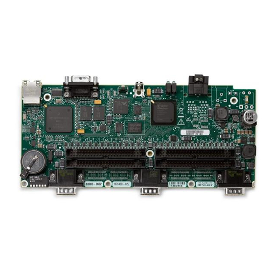
- Page 6 6 J9, Connector for C Series Module 1 14 LEDs 7 DIP Switches 15 J3, Power Connector 8 Backup Battery 16 P3, 3.3 V Digital I/O Figure 4. NI sbRIO-9601/9602/9602XT Parts Locator Diagram © National Instruments Corporation NI sbRIO-9601/9602/9602XT User Guide...
- Page 7 Tyco Electronics, — RS-232 Serial 0.318 in. (8.08 mm) high, 5747840-6 Port with 4-40 jacksockets P2, P3, P4, P5 50-pin polarized header plug, 3M, N2550-6002RB 3M, 8550-4500PL 0.100 × 0.100 in. (2.54 × 2.54 mm) NI sbRIO-9601/9602/9602XT User Guide ni.com...
- Page 8 D GND 14 13 Port5/DIO5 Pin 1 D GND 12 11 Port5/DIO4 Port5/DIO3 D GND Port5/DIO2 Port5/DIO1 Port5/DIO9 Port5/DIO0 Port5/DIOCTL D GND Figure 5. Pinout of I/O Connector P2, 3.3 V Digital I/O © National Instruments Corporation NI sbRIO-9601/9602/9602XT User Guide...
- Page 9 D GND 14 13 Port8/DIO0 Port8/DIOCTL 12 11 Port8/DIO9 D GND Port7/DIO8 D GND Port7/DIO7 D GND Port7/DIO6 D GND Port7/DIO5 Port7/DIO4 D GND Figure 6. Pinout of I/O Connector P3, 3.3 V Digital I/O NI sbRIO-9601/9602/9602XT User Guide ni.com...
- Page 10 D GND 14 13 Port0/DIO5 Pin 1 D GND 12 11 Port0/DIO4 Port0/DIO3 D GND Port0/DIO2 Port0/DIO1 Port0/DIO9 Port0/DIO0 Port0/DIOCTL D GND Figure 7. Pinout of I/O Connector P4, 3.3 V Digital I/O © National Instruments Corporation NI sbRIO-9601/9602/9602XT User Guide...
- Page 11 Port7/DIO9 Port7/DIO0 Port7/DIOCTL D GND Figure 8. Pinout of I/O Connector P5, 3.3 V Digital I/O Figure 9 shows the signals on J1, the RS-232 serial port. Figure 9. J1, RS-232 Serial Port Pin Assignments NI sbRIO-9601/9602/9602XT User Guide ni.com...
- Page 12 If you want to use the device on a subnet other than the one the host computer is on, first connect the device on the same subnet as the host computer. Use DHCP to assign an IP address or reassign a static IP address © National Instruments Corporation NI sbRIO-9601/9602/9602XT User Guide...
- Page 13 Complete the following steps to connect a power supply to the device. Refer to Figure 10 for an illustration of the power supply connections. Common (–) Voltage Figure 10. Connecting a Power Supply NI sbRIO-9601/9602/9602XT User Guide ni.com...
-
Page 14: Boot Options
Note If you want a VI to run when loaded to the FPGA, complete the following steps. Right-click the FPGA Target item in the Project Explorer window in LabVIEW. Select Properties. © National Instruments Corporation NI sbRIO-9601/9602/9602XT User Guide... -
Page 15: Configuring Dip Switches
6 NO FPGA Figure 11. DIP Switches All of the DIP switches are in the OFF (up) position when the NI sbRIO device is shipped from National Instruments. SAFE MODE Switch The position of the SAFE MODE switch determines whether the embedded LabVIEW Real-Time engine launches at startup. - Page 16 LabVIEW. To run an application at startup, push the NO APP switch to the OFF position, create an application using the LabVIEW Application Builder, and configure the application in LabVIEW to launch at startup. For more information about automatically launching VIs at © National Instruments Corporation NI sbRIO-9601/9602/9602XT User Guide...
-
Page 17: Using The Reset Button
Autoload VI on device reboot boot option. Refer to the Boot Options section for more information. Understanding LED Indications 1 FPGA 2 USER 3 POWER 4 STATUS Figure 12. NI sbRIO Device LEDs NI sbRIO-9601/9602/9602XT User Guide ni.com... -
Page 18: Power Led
The device is in safe mode because the SAFE MODE DIP switch is in the ON position. Refer to the Configuring DIP Switches section for information about the SAFE MODE DIP switch. © National Instruments Corporation NI sbRIO-9601/9602/9602XT User Guide... - Page 19 Note If the device is restored to the factory network settings, the LabVIEW run-time engine does not load. You must reconfigure the network settings and reboot the device for the LabVIEW run-time engine to load. NI sbRIO-9601/9602/9602XT User Guide ni.com...
- Page 20 The NI sbRIO devices are tested with all 110 DIO channels driving 3 mA DC loads, for a total of 330 mA sourcing from the FPGA. The FPGA uses minimum 8 mA drivers, but the devices are not characterized for loads higher than 3 mA. © National Instruments Corporation NI sbRIO-9601/9602/9602XT User Guide...
-
Page 21: Signal Integrity
P2–P5. Each pin on the headers is rated for 2 A, but a typical 28 AWG ribbon cable is rated for only 225 mA per conductor. The OEM user is responsible for determining cabling requirements and ensuring that current limits are not exceeded. NI sbRIO-9601/9602/9602XT User Guide ni.com... -
Page 22: Specifications
Unless otherwise noted, the following specifications are typical for the range –40 to 85 °C for the NI sbRIO-9602XT, and for the range –20 to 55 °C for the NI sbRIO-9601 and NI sbRIO-9602. Network Network interface........10BaseT and 100BaseTX Ethernet Compatibility ......... - Page 23 Memory Nonvolatile memory NI sbRIO-9601 ........128 MB minimum NI sbRIO-9602/9602XT....256 MB minimum System memory NI sbRIO-9601 ........64 MB minimum NI sbRIO-9602/9602XT....128 MB minimum For information about the life span of the nonvolatile memory and about best practices for using nonvolatile memory, go to and enter ni.com/info...
- Page 24 Maximum hold current at 70 °C ..20 mA Maximum hold current at 85 °C (NI sbRIO-9602XT only) ....3 mA Trip current at 25 °C ....... 71 mA Resistance at 25 °C ......33 Ω ±20% © National Instruments Corporation NI sbRIO-9601/9602/9602XT User Guide...
- Page 25 Resistance-temperature characteristics, typical curve Resistance-Temperature Characteristics Typical Curve 1000 –40 –20 Temperature (°C) NI sbRIO-9601/9602/9602XT User Guide ni.com...
-
Page 26: Power Limits
........3.3 W; each installed C Series CSer module consumes up to 1.1 W The NI sbRIO device is 1–2% more efficient with a 19 V supply than with a 30 V supply. © National Instruments Corporation NI sbRIO-9601/9602/9602XT User Guide... -
Page 27: Safety Voltages
Total power requirement = 17.92 W • For an NI sbRIO-9601 with one installed board-only C Series module, 330 mA total current through the 3.3 V DIO pins, and no 5 V output used, calculate the total power requirement as follows: = 6.0 W... -
Page 28: Environmental Management
(For information about China RoHS compliance, go to ni.com/environment/rohs_china Environmental The NI sbRIO-9601/9602/9602XT is intended for indoor use only. Ambient temperature in enclosure (IEC 60068-2-1, IEC 60068-2-2) NI sbRIO-9601/9602 ...... –20 to 55 °C NI sbRIO-9602XT ......–40 to 85 °C Storage temperature (IEC 60068-2-1, IEC 60068-2-2)... -
Page 29: Physical Characteristics
Table 4. Ethernet Cable Wiring Connections Connector 2 Connector 2 Connector 1 (Normal) (Crossover) white/orange white/orange white/green orange orange green white/green white/green white/orange blue blue blue white/blue white/blue white/blue green green orange white/brown white/brown white/brown brown brown brown NI sbRIO-9601/9602/9602XT User Guide ni.com... -
Page 30: Where To Go For Support
Pin 8 Pin 1 Figure 14. Ethernet Connector Pinout Where to Go for Support The National Instruments Web site is your complete resource for technical support. At you have access to everything from ni.com/support troubleshooting and application development self-help resources to email and phone assistance from NI Application Engineers. - Page 31 Thailand 662 278 6777, Turkey 90 212 279 3031, United Kingdom 44 (0) 1635 523545 LabVIEW, National Instruments, NI, ni.com, the National Instruments corporate logo, and the Eagle logo are trademarks of National Instruments Corporation. Refer to the Trademark Information at ni.com/trademarks for other National Instruments trademarks.
Need help?
Do you have a question about the sbRIO-9601 and is the answer not in the manual?
Questions and answers