Table of Contents
Advertisement
KENDRION
INDUSTRIAL BRAKES
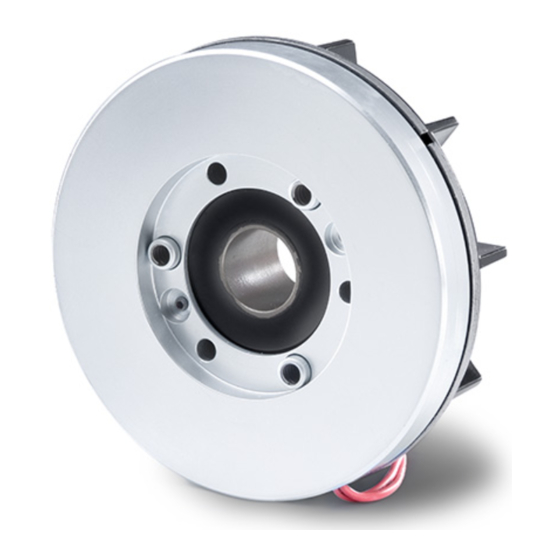
EEX Line
Spring-applied single-disc brake
Operating Instructions 76..G..B00
Types: 76 14G10B00 76 16G10B00 76 24G10B00 76 26G10B00
76 14G11B00 7616G11B00 76 24G11B00 76 26G11B00
76 14G13B00 76 16G13B00 76 24G13B00 76 26G13B00
76 14G16B00 76 16G16B00 76 24G16B00 76 26G16B00
76 14G19B00 76 16G19B00 76 24G19B00 76 26G19B00
76 14G24B00 76 16G24B00 76 24G24B00 76 26G24B00
Advertisement
Table of Contents

Subscribe to Our Youtube Channel
Related Manuals for Kendrion EEX Series


Summary of Contents for Kendrion EEX Series
- Page 1 KENDRION INDUSTRIAL BRAKES EEX Line Spring-applied single-disc brake Operating Instructions 76..G..B00 Types: 76 14G10B00 76 16G10B00 76 24G10B00 76 26G10B00 76 14G11B00 7616G11B00 76 24G11B00 76 26G11B00 76 14G13B00 76 16G13B00 76 24G13B00 76 26G13B00 76 14G16B00 76 16G16B00 76 24G16B00 76 26G16B00...
-
Page 2: Table Of Contents
Product number / type number / version number ................33 Specialist repair shops ........................33 Revision history ........................... 33 Document information: Issued by: Kendrion (Villingen) GmbH Last updated: 13/03/2020 Replaces document: - Replaces the issue dated: 01/04.2018 Document type: translation of original German operating Document status: released instructions BA 76 ..G..B00... -
Page 3: General
Should any queries arise with respect to torques, torque variations, installation position, wear, wear reserve, switching work, break-in conditions, release range, ambient conditions and the like, please contact Kendrion (Villingen) and ask for clarification before starting to use the brake. Spring-applied brakes are not ready-to-use devices, but are intended to be incorporated into or assembled with other equipment. -
Page 4: Declaration Of Incorporation (In Accordance With Annex Ii, Part 1, Section B Of Machinery Directive 2006/42/Ec)
Annex VII, part B of Machinery Directive 2006/42/EC. The manufacturer undertakes to submit an electronic copy of the relevant technical documentation compiled for the partly completed machinery if reasonably requested by national authorities. Manufacturer: Kendrion (Villingen) GmbH Person authorized Dominik Hettich Wilhelm-Binder-Str. -
Page 5: Declarations Of Conformity
Directive 2014/34/EU (ATEX Directive). This declaration will cease to be valid if modifications are made to the product without prior permission from the manufacturer. Manufacturer: Kendrion (Villingen) GmbH Person authorized: Dominik Hettich Wilhelm-Binder-Str. 4-6... -
Page 6: Directives 2014/35/Eu (Low Voltage Directive) And 2011/65/Eu (Rohs Directive)
2011/65/EU (RoHS Directive). The products are classified as category 11 equipment subject to Directive 2011/65/EU (RoHS Directive). This declaration will cease to be valid if modifications are made to the product without prior permission from the manufacturer. Manufacturer: Kendrion (Villingen) GmbH Person authorized: Dominik Hettich Wilhelm-Binder-Str. 4-6... -
Page 7: Product Description
2. Product description 2.1 Operating principle The spring-applied single-disc brake is designed to operate dry. The force generated by an electromagnetic field is utilized to overcome the braking effect produced by the spring force. The spring-applied single-disc brake engages in unpowered condition and releases when AC voltage is applied. The form-fit connection between the friction disc and hub and the connection of the hub with the machine shaft (e.g. - Page 8 List of reference numerals in Fig. 9/1: Solenoid housing 13.3 Angle Junction box Field coil 13.4 Countersunk screw Cover Armature 13.5 Plate Socket head cap screw Flange 13.6 Socket head cap screw Spring washer Compression spring 13.7 Connecting cable (microswitch) Hand release Friction disc Circlip (outer ring)
- Page 9 Operating Instructions BA 76..G..B00 // Last updated: 13/03/2020 // Page 9 of 34...
-
Page 10: Installation
3. Installation 3.1 Mechanical installation Slip the hub (17) of the spring-applied single-disc brake on a shaft (tolerance h6) provided with a feather key to DIN 6885, sheet 1. As the hub (17) is firmly fitted to the brake, it need not be axially secured on the machine shaft (e.g. motor shaft). -
Page 11: Installation Of The Hand Release (29) (Brake Types With Hand Release)
3.2 Installation of the hand release (29) (brake types with hand release) Insert the hand release handle (29) into the square socket of the two cams (29.1) that are firmly fitted to the circumference of the solenoid housing (1.1). Ensure that the handle is correctly positioned. The mechanical release forces F and the maximum permissible release forces (actuation forces) F are specified in Table 11/1. -
Page 12: Ac Power Supply
Attention! When fixing the cover (26) to the junction box (25), the M tightening torques for the socket head cap screws specified in Table 15/1 must be strictly observed. The flat seal (9) and spring washer (28) must be installed as shown in Fig. - Page 13 AC side switching DC side switching Built-in rectifier Brake field coil (1.2) Control relay for brake Safety switches (microswitch contacts (only brake types with microswitch (13) and thermoswitches (11 & 12)) Control relay for machine (e.g. motor) Built-in bridge rectifier with DC side disconnection Fig.
-
Page 14: Microswitch (13) And Thermoswitch (11 & 12) Connection
Attention! To avoid damage (e.g. burns or fusing of contacts) to the external circuitry in case of DC side brake switching, additional protection elements (e.g. varistors, spark arresters, etc.) are necessary. Warning! Work on the brake must only be carried out by suitably qualified personnel. Make sure that no voltage is applied during brake connection. -
Page 15: Electromagnetic Compatibility
Size tightening torque [Nm] for socket head cap screws (20) of cover (7) tightening torque [Nm] for socket head cap screws (22) of flange (3) tightening torque [Nm] for socket head cap screws (27) of junction box (25) cover (26) Table 15/1: Tightening torques for socket head cap screws Note! Machinery-specific regulations and requirements (e.g. - Page 16 EN 61000-4-4 Fast transients (burst): The brakes comply at least with severity level 3 without requiring additional measures. The built-in rectifier conforms to severity level 3 without additional measures. EN 61000-4-5 Surge: The brakes comply at least with severity level 3 without requiring additional measures. The built-in rectifier conforms to severity level 3 without additional measures.
-
Page 17: Set-Up And Start-Up
E76 00A0030 000 recommended by Kendrion. This can also be accomplished by using a sealing device available from Kendrion. In this case, the maximum possible protection rating is IP 56. After connection of the brake, a functional test must be performed to check that the friction disc (5) moves smoothly. -
Page 18: M 2 Rated Torque Adjustments
Warning! Before starting the machine (e.g. motor) test run without driven components, the feather key (if used) must be secured in such a way that it cannot be hurled out. Ensure that the shaft is not exposed to load torques. Before the machine is re-started, the brake must be de-energized. -
Page 19: Maintenance
Warning! Any adjustment of the rated torque must be performed by the manufacturer or by authorized specialist personnel. 4. Maintenance 4.1 Checks and service The spring-applied single-disc brake does not require any particular maintenance except that the friction disc (5) must be replaced when worn (see “Technical specifications” for information on the maximum air gap s and that the safety switches (microswitch (13) and thermoswitches (11 &... - Page 20 Friction disc (5) replacement: Remove the self-locking nut (31) from the socket head cap screws (32). Loosen the socket head cap screws (22) provided on the flange (3) and remove the flange (3). Remove the friction disc (5) from the hub (17) and replace it by a new one.
- Page 21 Microswitch (13) adjustment or replacement (relevant only for brake types equipped with microswitch): The spring-applied single-disc brake must be released electrically before the microswitch (13) can be adjusted. Loosen the socket head cap screws (20) provided on the cover (7) and remove the cover (7). Unscrew the locknut (13.1) and turn the set screw (13.2) clockwise until the microswitch (13) switches (slight audible click or contact closure between contacts 5 and 6 (see Section 3.3).
-
Page 22: Spare Parts And Accessories
Caution! Whenever inspection and maintenance work is carried out, ensure that the machine (e.g. motor) is secured against accidental or unintentional start-up. • no load torque acts on the shaft. • the lock provided to prevent accidental start-up of the machine (e.g. motor) is removed after completion •... -
Page 23: Emissions
Note! The environmental conditions specified in Table 23/1 and in EN IEC 60721-3-2 / EN IEC 60721-3-1 must be considered during transport and storage of the brake, especially when long-term storage is envisaged. Environmental conditions Conditions for storage Conditions for transport to EN IEC 60721-3-1 to EN IEC 60721-3-2 Mechanical environmental conditions... -
Page 24: Troubleshooting
7. Troubleshooting Fault Cause Corrective actions Check the air gap. Install a new friction disc, if Air gap too large • necessary. Check the electrical connection and correct faults, if • No voltage applied to brake found. Check the field coil supply voltage and correct faults, if •... -
Page 25: Safety
Kendrion and ask for clarification before using the brake. Retrofitting or modification work to be carried out on the brake is subject to the approval from Kendrion (Villingen). -
Page 26: Set-Up
8.2.1 Set-up Requirements in terms of the permissible number of switching operations per hour and the maximum switching work per switching operation (see Fig. 32/1) specified in the technical specifications must be strictly observed during the set-up of machines and plant (jog mode). Failure to observe these instructions may irreversibly diminish the braking effect and cause malfunctions. -
Page 27: Maintenance, Repair And Replacement
Notice! During brake operation, ensure that the coil temperature does not rise above the permissible limit temperature applicable to the insulating materials of the specified insulation class (see Table 30/1). Fast cooling of the field coil with scavenging air is not allowed. Ensure that the permissible relative humidity range (see Table 31/2) is not exceeded. -
Page 28: Definitions
9. Definitions (based on: DIN VDE 0580:2011-11, not exhaustive) Switching torque M torque acting on the shaft during brake or clutch slip Rated torque M switching torque specified by the manufacturer to identify the brake. The rated torque M is the mean value of at least 3 measurements of the maximum switching torque M after completion of the transient response. - Page 29 Overtemperature ∆ϑ difference between the temperature of the electromagnetic device or a part thereof and the ambient temperature Limit temperatures of coil insulating materials in accordance with DIN VDE 0580. The individual insulating materials are classified by insulation classes to DIN IEC 60085. Rated voltage U supply voltage specified by the manufacturer for voltage windings to identify the device or component...
-
Page 30: Technical Specifications
10. Technical specifications Product built and tested to DIN VDE 0580 Size Rated torque M [Nm] Max. speed n [rpm] 6000 6000 3600 3600 3600 3600 Max. switching power P [kJ/h] Apparent power P [VA] Coupling time t [ms] Disconnection time t [ms] Moment of inertia J –... - Page 31 Size Max. rated voltage [VAC] Rated current (cos ϕ=1.0) [A] Rated current (cos ϕ=0.6) [A] Service life (switching operations) 5000 Contact type normally closed (NC) Nominal temperature (switching temperature) thermoswitch 11 (flange (3)) [°C] Nominal temperature (switching temperature) thermoswitch 12 (coil (1.2)) [°C] Min.
- Page 32 Explanations on the technical specifications: (maximum switching work) is the switching work that 100000 must not be exceeded during braking operations at maximum speeds of 1500 rpm. Braking operations at speeds greater than 1500 rpm substantially reduce the Size 24/19 Gr.
-
Page 33: Product Versions (Types)
So the version number identifies the relevant brake model. Example: Type number: 76 26G11B00 Version number: 0001 Product number: 76 24G11B00-0001 13. Specialist repair shops Kendrion (Villingen) GmbH Wilhelm-Binder-Straße 4-6 78048 Villingen-Schwenningen Germany Tel: +49 (0)7721 877-1417 14. Revision history... - Page 34 Betriebsanleitung 76 43119H03 Operating Instructions BA 76..G..B00 // Last updated: 13/03/2020 // Page 1 of 34...
Need help?
Do you have a question about the EEX Series and is the answer not in the manual?
Questions and answers