
Subscribe to Our Youtube Channel
Related Manuals for Kendrion INTORQ BFK458-ATEX


Summary of Contents for Kendrion INTORQ BFK458-ATEX
- Page 1 INTORQ BFK458-ATEX Spring-applied brake with electromagnetic release Translation of the Original Operating Instructions www.kendrion.com...
-
Page 2: Legal Regulations
The warranty conditions can be found in the terms and conditions of Kendrion INTORQ GmbH. ¾ Warranty claims must be made to Kendrion INTORQ immediately after the defects or faults are detected. ¾ The warranty is void in all cases when liability claims cannot be made. -
Page 3: Spring-Applied Brakes Of Type Bfk458-06
Spring-applied brakes of type BFK458-06...25 Design E Design N Double spring-applied brake Kendrion INTORQ | BA 14.0217 | 07/2021... -
Page 4: Product Key
Kendrion INTORQ does not accept any liability for deficiencies claimed subsequently. ¾ Claim visible transport damage immediately to the deliverer. ¾ Claim visible defects or incompleteness of the delivery immediately to Kendrion INTORQ. Kendrion INTORQ | BA 14.0217 | 07/2021... -
Page 5: Table Of Contents
3.2.6 Double spring-applied brake........................ 18 3.3 Function ................................ 18 3.4 Braking and release ............................ 19 3.5 Brake torque reduction............................ 19 3.6 Optional configuration ............................ 19 3.6.1 Hand-release (optional) ......................... 19 4 Project planning notes ............................ 20 Kendrion INTORQ | BA 14.0217 | 07/2021... - Page 6 5 Technical specifications............................ 21 5.1 General information............................ 21 5.2 Possible applications of the Kendrion INTORQspring-applied brake.............. 21 5.3 Brake torques.............................. 22 5.4 Characteristics .............................. 23 5.5 Operating times.............................. 28 5.6 Friction work / operating frequency ........................ 30 5.7 Dust explosive atmosphere (zone 22: non-conductive dusts)................ 30 5.8 Gas explosive atmosphere (zone 2) ........................
- Page 7 7.7.4 Permissible current load at ambient temperature.................. 62 8 Commissioning and operation .......................... 63 8.1 Possible applications of the Kendrion INTORQ spring-applied brake.............. 63 8.2 Function checks before initial commissioning .................... 64 8.2.1 Function check of the brake ........................ 64 8.2.2 Release / voltage control ........................
-
Page 8: General Information
Important notice about ensuring smooth op- Notice erations or other key information. Safety instructions and notices The following icons and signal words are used in this document to indicate dangers and important safety information: Kendrion INTORQ | BA 14.0217 | 07/2021... -
Page 9: Terminology Used
Terminology used Term In the following text used for Spring-applied brake Spring-applied brake with electromagnetic release Drive systems with spring-applied brakes and other drive compo- Drive system nents Kendrion INTORQ | BA 14.0217 | 07/2021... -
Page 10: Abbreviations Used
Rated air gap Minimum air gap Lmin Maximum air gap Lmax Engagement time, sum of the delay time and braking torque: rise time Disengagement time, time from switching the stator until reaching 0.1 M Kendrion INTORQ | BA 14.0217 | 07/2021... - Page 11 Over-excitation period Voltage V DC Holding voltage, after voltage change-over V DC Release voltage, before voltage change-over Rated coil voltage; in the case of brakes requiring a voltage change-over, V DC equals U Kendrion INTORQ | BA 14.0217 | 07/2021...
-
Page 12: Safety Instructions
Only use original spare parts from the manufacturer. Keep the following in mind during the initial commissioning and during operation: ¾ Depending on the degree of protection, Kendrion INTORQ components may have both live (voltage carrying), moving and rotating parts. Such components require appropriate safety mechanisms. ¾... -
Page 13: Safety Notices For Use In Potentially Explosive Areas
ATEX name plate for the dust zone must be moni- tored on the brake's magnet housing using a suitable temperature measurement mechanism. If there is no available knowledge of the occurring temperatures, then Kendrion INTORQ is no longer responsible for this ATEX certification. -
Page 14: Product Description
3.1.1 Standard applications Kendrion INTORQ components are intended for use in machinery and facilities. They may only be used for purposes as specified in the order and confirmed by Kendrion INTORQ. The Kendrion INTORQ com- ponents may only be operated under the conditions specified in these Operating Instructions. They may never be operated beyond their specified performance limits. -
Page 15: Design
¾ Use the brake with a cover ring (without a condensate drain hole) and consequently also with the Kendrion INTORQ flange/friction plate and the corresponding ring nut for attaching the cover ring (refer to the section Cover ring assembly, Page 52). ¾... -
Page 16: Basic Module E
Design of a INTORQ BFK458 spring-applied brake Basic module E (complete stator) + rotor + hub + flange Tappet Torque adjustment ring Stator Socket-head cap screw Hand-release (optional) Sleeve bolt Flange Rotor Pressure spring Armature plate Kendrion INTORQ | BA 14.0217 | 07/2021... -
Page 17: Basic Module N
The long-life design can be configured modularly for size 6 to size 12 in combination with the specified rated torques. The specifications are as follows: ¾ The stator corresponds to the design N. ¾ Rear bores and extensions are not possible. Kendrion INTORQ | BA 14.0217 | 07/2021... -
Page 18: Double Spring-Applied Brake
The asbestos-free friction linings ensure a safe braking torque and low wear. To release the brake, the armature plate is released electromagnetically from the rotor. The rotor, shifted axially and balanced by the spring force, can rotate freely. Kendrion INTORQ | BA 14.0217 | 07/2021... -
Page 19: Braking And Release
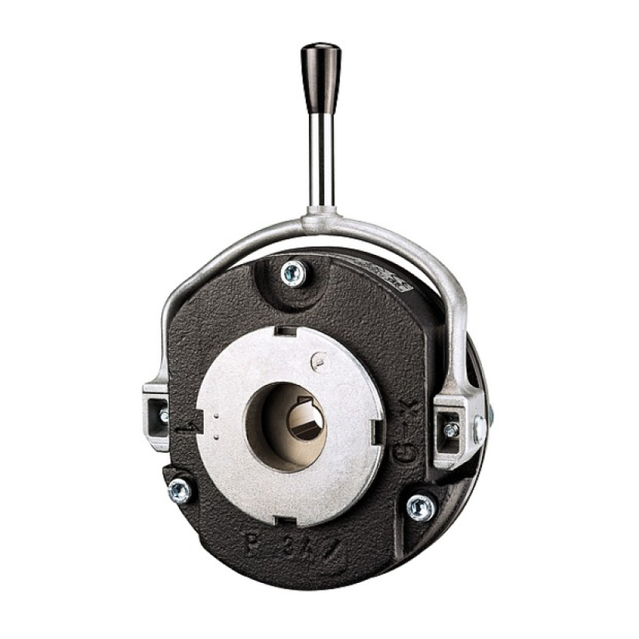
Optional configuration 3.6.1 Hand-release (optional) To temporarily release the brake when there is no electricity available, a hand-release function is available as an option. The hand-release function can also be retrofitted. Kendrion INTORQ | BA 14.0217 | 07/2021... -
Page 20: Project Planning Notes
This would result in higher temperatures, which would then pose a risk of igni- tion. ¾ Use only original Kendrion INTORQ friction parts (flange and armature plate) and standard friction lin- ings (ST) for the ATEX brake. ¾... -
Page 21: Technical Specifications
ATEX name plate for the dust zone must be moni- tored on the brake's magnet housing using a suitable temperature measurement mechanism. If there is no available knowledge of the occurring temperatures, then Kendrion INTORQ is no longer responsible for this ATEX certification. -
Page 22: Brake Torques
Dust explosive atmosphere (zone 22: non-conductive dusts), Page 30 and Gas explosive atmosphere (zone 2), Page 32, shall be applicable. Notice A version of the double spring-applied brake using HFC (high-friction coefficient) linings is not permitted. Kendrion INTORQ | BA 14.0217 | 07/2021... -
Page 23: Characteristics
0.45 11.5 10.0 13.0 12.0 16.0 1.25 0.75 15.5 20.0 19.5 Tab. 4: Characteristics for air gap specifications The friction lining is sized so that the brake can be adjusted at least five times. Kendrion INTORQ | BA 14.0217 | 07/2021... - Page 24 With the double spring-applied brake design, when working with braking torques which are greater than the standard braking torque, you need to check the screws connecting the first brake. Please consult with Kendrion INTORQ! Kendrion INTORQ | BA 14.0217 | 07/2021...
- Page 25 Coil voltage Coil resistance Rated current ±8% [Ω] 28.8 0.83 460.8 0.21 530.5 0.194 1445 0.114 1620 0.111 1805 0.105 2101 0.098 1.04 0.26 424.4 0.242 1156 0.147 1296 0.138 1444 0.131 1681 0.121 Kendrion INTORQ | BA 14.0217 | 07/2021...
- Page 26 722.5 0.235 0.222 902.5 0.210 1051 0.195 11.5 2.08 184.3 0.52 200.2 0.514 0.294 611.3 0.294 0.263 792.9 0.258 10.5 2.29 167.6 0.573 189.5 0.543 525.5 0.323 589.1 0.305 601.7 0.315 750.5 0.292 Kendrion INTORQ | BA 14.0217 | 07/2021...
- Page 27 262.7 0.647 294.6 0.611 328.2 0.578 382.1 0.536 Tab. 8: Rated data for coil power Coil power at 20 °C in W, deviation up to +10% is possible depending on the selected connection voltage. Kendrion INTORQ | BA 14.0217 | 07/2021...
-
Page 28: Operating Times
[ms] Tab. 9: Switching energy - operating frequency - operating times These operating times are specified for usage of Kendrion INTORQ bridge/half-wave rectifiers and coils with a con- nection voltage of 205 V DC at s and 0.7 I Kendrion INTORQ | BA 14.0217 | 07/2021... - Page 29 Spark suppressors are available for the rated voltages. Notice Kendrion INTORQ half-wave and bridge rectifiers and spark suppressors have not been de- signed for use in potentially explosive atmospheres. If the use of these electrical components is necessary, they must be installed within a control cabinet that is outside the explosive at- mosphere.
-
Page 30: Friction Work / Operating Frequency
Dust explosive atmosphere (zone 22: non-conductive dusts) 100000 10000 1000 1000 Operating frequency S [h ] Fig. 5: Friction work as a function of the operating frequency BFK-458-ATEX for dust atmospheres Kendrion INTORQ | BA 14.0217 | 07/2021... - Page 31 10986 10799 21329 20317 28727 27237 34117 32181 48216 43233 73755 65483 110150 93224 Tab. 10: Permissible friction work [J], depending on the number of switching operations that is typical for facility acceptance tests Kendrion INTORQ | BA 14.0217 | 07/2021...
-
Page 32: Gas Explosive Atmosphere (Zone 2)
800 rpm 100000 10000 1000 1000 Operating frequency S [h ] Fig. 7: Friction work as a function of the operating frequency for the BFK-458-ATEX, for gas atmospheres, for the speed 1500 rpm Kendrion INTORQ | BA 14.0217 | 07/2021... - Page 33 1800 rpm 100000 10000 1000 1000 Operating frequency S [h ] Fig. 9: Friction work as a function of the operating frequency for the BFK-458-ATEX, for gas atmospheres, for the speed 2500 rpm Kendrion INTORQ | BA 14.0217 | 07/2021...
- Page 34 5398 5140 3196 11289 7179 6938 6673 3700 10457 6983 6795 7855 3692 12401 8585 8331 8076 4000 11812 8408 7855 7855 3988 14385 9987 9731 9472 4599 13702 9817 9521 9213 4572 Kendrion INTORQ | BA 14.0217 | 07/2021...
-
Page 35: Example Calculation For The Charts
The user must ensure compliance with EMC Directive 2014/30/EC using appropriate controls and switching devices. NOTICE If a Kendrion INTORQ rectifier is used for the DC switching of the spring-applied brake and if the switching frequency exceeds five switching operations per minute, the use of a mains filter is required. -
Page 36: Emissions
Brake completely installed Stator (not attached to the motor) Fig. 11: Positions of the adjustment dimensions that must be checked +0.1 / -0.05 +0.1 Size [mm] [mm] Tab. 12: Adjustment setting for hand-release Kendrion INTORQ | BA 14.0217 | 07/2021... -
Page 37: Labels On Product
Rated voltage 32 NM Rated torque 1 pc. Qty. per box 40 W Rated power 25 H7 Hub diameter 17.03.21 Packaging date Anti-rust packaging: keep friction surface free of Addition grease! CE mark Kendrion INTORQ | BA 14.0217 | 07/2021... - Page 38 205 V DC Rated voltage 40 W Rated power 20 H7 Hub diameter No. 15049627 ID number 32 NM Rated torque 17.03.21 Date of manufacture Data matrix code CE mark CSA/CUS acceptance UL mark Kendrion INTORQ | BA 14.0217 | 07/2021...
-
Page 39: Atex Marking
Name plate ATEX holding brake (an example) Labeling Meaning II 3G Designation label according to ATEX II 3D directive 2014/34/EU Ex nA IIC T4 Gc X Designation label according to DIN EN Ex tc IIIC 120°C Dc X 60079-0 Kendrion INTORQ | BA 14.0217 | 07/2021... -
Page 40: Mechanical Installation
DANGER Danger of explosion Increased temperatures on the surfaces and in the friction gap can result when the maxi- mum friction work and operating frequencies specified by Kendrion INTORQ are ex- ceeded. These can lead to ignition. ¾ Operation is only permitted within the specified specifications. -
Page 41: Design Of End Shield And Shaft
The diameter of the shaft shoulder must not be greater than the tooth root diameter of the hub. ¾ The form and position tolerances apply only to the materials mentioned. Consult with Kendrion IN- TORQ before using other materials; written confirmation is required for such usage. -
Page 42: Tools
Feeler gage Preparing the installation 1. Remove the packaging from the spring-applied brake and dispose of it properly. 2. Check the delivery for completeness. 3. Check the name plate specifications (especially the rated voltage)! Kendrion INTORQ | BA 14.0217 | 07/2021... -
Page 43: Installing The Hub Onto The Shaft
¾ If you have deviating operating conditions (e.g. additional load spectra with engaged brake), please contact Kendrion INTORQ for the proper dimensioning of the hub-side key connection. ¾ Secure the hub against axial displacement after you install it (e.g. with a circlip). -
Page 44: Mounting The Brake
Mounting the rotor (without friction plate / without brake flange) Fig. 16: Assembly of the rotor Rotor End shield 1. Push the rotor on the hub. 2. Check if the rotor can be moved manually. Kendrion INTORQ | BA 14.0217 | 07/2021... - Page 45 Characteristics: screw kit for brake assembly on separately screwed-on flange, Page 24 ). 4. Remove the terminal clips and dispose of properly. Fig. 18: Tightening the screws with a torque wrench Kendrion INTORQ | BA 14.0217 | 07/2021...
- Page 46 7. Use a torque wrench to tighten the socket head cap screws (refer to the Figure Tightening the screws with a torque wrench, Page 45). NOTICE Tightening torques: refer to the table Characteristics: screw kit for brake assembly on sep- arately screwed-on flange, Page 24. Kendrion INTORQ | BA 14.0217 | 07/2021...
-
Page 47: Installing The Friction Plate (Optional)
2. Align the hole circle along the screw-in holes. 3. Mount the brake using the appropriate set of screws (refer to the figures in the chapters Mounting the brake, Page 44 and Spare parts list, Page 76 ). Kendrion INTORQ | BA 14.0217 | 07/2021... -
Page 48: Installing The Flange (Variants: Size 06 - 16)
Tighten the screws evenly (for tightening torques, refer to the table Characteristics: screw kit for brake assembly on separately screwed-on flange, Page 24 ). 3. Use the three screws to screw the flange to the end shield. Kendrion INTORQ | BA 14.0217 | 07/2021... -
Page 49: Installing The Flange (Variants: Size 18 - 20)
Fig. 22: Flange mounting for sizes 18 – 20 According to the table Characteristics: screw kit for brake assembly on separately screwed-on flange, Page 24 1. Place the flange against the end shield. Kendrion INTORQ | BA 14.0217 | 07/2021... -
Page 50: Installing The Flange (Variants: Size 25)
The screws must not press against the end shield. Fig. 23: Flange mounting for size 25 Hex screw Flange End shield According to the table Characteristics: screw kit for brake assembly on separately screwed-on flange, Page 24 Kendrion INTORQ | BA 14.0217 | 07/2021... -
Page 51: Installing The Double Spring-Applied Brake
Charac- teristics: screw set, intermediate flange installation for double spring-applied brake , Page 25 (in the column "Screw kit for mounting an adapter flange on a stator"). Kendrion INTORQ | BA 14.0217 | 07/2021... -
Page 52: Cover Ring Assembly
NOTICE With the double spring-applied brake design, when working with braking torques which are greater than the standard braking torque, you need to check the screws connecting the first brake. Please consult with Kendrion INTORQ! Cover ring assembly Fig. 25: Cover ring assembly... -
Page 53: Installing The Shaft Sealing Ring
No grease should be allowed to contact the friction surfaces. ¾ When assembling the stator, push the shaft sealing ring carefully over the shaft. The shaft should be located concentrically to the shaft sealing ring Kendrion INTORQ | BA 14.0217 | 07/2021... -
Page 54: Mounting The Hand-Release (Retrofitting)
7. Set the gap s evenly using the hex head screws and the feeler gauge. Refer to the table Ad- justment setting for hand-release, Page 36 for the values for the dimension s Kendrion INTORQ | BA 14.0217 | 07/2021... -
Page 55: Electrical Installation
The terminal pin sequence shown here does not match the actual order. Notice Kendrion INTORQ half-wave and bridge rectifiers and spark suppressors have not been de- signed for use in potentially explosive atmospheres. If the use of these electrical components is necessary, they must be installed within a control cabinet that is outside the explosive at- mosphere. -
Page 56: Ac Switching At The Motor - Extremely Delayed Engagement
Supply: Phase-phase Bridge rectifier Half-wave rectifier BEG-1xx: U [V DC] = 0.9 • U [V AC] BEG-2xx: U [V DC] = 0.45 • U [V AC] Not recommended for most regional/national high-voltage mains voltages. Kendrion INTORQ | BA 14.0217 | 07/2021... -
Page 57: Dc Switching At The Motor - Fast Engagement
Supply: Phase-phase Bridge rectifier Half-wave rectifiers BEG-1xx: U [V DC] = 0.9 • U [V AC] BEG-2xx: U [V DC] = 0.45 • U [V AC] Not recommended for most regional/national high-voltage mains voltages. Kendrion INTORQ | BA 14.0217 | 07/2021... -
Page 58: Ac Switching At Mains - Delayed Engagement
Supply: Phase-phase Bridge rectifier Half-wave rectifiers BEG-1xx: U [V DC] = 0.9 • U [V AC] BEG-2xx: U [V DC] = 0.45 • U [V AC] Not recommended for most regional/national high-voltage mains voltages. Kendrion INTORQ | BA 14.0217 | 07/2021... -
Page 59: Dc Switching At Mains - Fast Engagement
BEG-24x: U [V DC] = 0.45 • U [V AC] Spark suppressor: 14.198.00.xx (required once, select position) For most regional/national high-voltage mains voltages, this only makes sense for supplies on L1 and N. Kendrion INTORQ | BA 14.0217 | 07/2021... -
Page 60: Minimum Bending Radius For The Brake Connection Cable
The bridge-half-wave rectifiers are used to supply electromagnetic DC spring-applied brakes which are ap- proved for use with such rectifiers. Other use is only permitted with the approval of Kendrion INTORQ. Once a set overexcitation period has elapsed, the bridge-half-wave rectifiers switch over from bridge recti- fication to half-wave rectification. -
Page 61: Assignment: Bridge/Half-Wave Rectifier - Brake Size
1 min 1 Nom 1 max [V~] [V~] [V~] BEG-561-255-030 0.430 0.300 0.270 BEG-561-255-130 1.870 1.300 1.170 BEG-561-440-030-1 0.75 0.500 0.300 0.270 BEG-561-440-130 2.300 1.300 1.200 Tab. 15: Data for bridge/half-wave rectifier type BEG-561 Kendrion INTORQ | BA 14.0217 | 07/2021... -
Page 62: Reduced Switch-Off Times
Delayed engagement Fast engagement Mains Bridge Coil Mains Coil 7.7.4 Permissible current load at ambient temperature Fig. 37: Permissible current load If screwed to metal surface (good heat dissipation) For other installations (e.g. with adhesive) Kendrion INTORQ | BA 14.0217 | 07/2021... -
Page 63: Commissioning And Operation
Commissioning and operation Commissioning and operation Possible applications of the Kendrion INTORQ spring-applied brake NOTICE In case of high humidity: If condensed water and moisture are present, provide for an ap- propriate ventilation for the brake to ensure that all friction components dry quickly. -
Page 64: Function Checks Before Initial Commissioning
. The air gap must be zero and the rotor must rotate freely. 6. Switch off the supply to the motor and brake securely. 7. Connect the bridges to the motor terminals. Remove any extra neutral conductor. Kendrion INTORQ | BA 14.0217 | 07/2021... -
Page 65: Testing The Hand-Release Functionality
This operational test must also be carried out! Fig. 38: Turning direction of the lever Size Hand force [N] Hand force [N] Standard braking torque Maximum braking torque 250* 330* 350* Tab. 16: Actuating forces * When used with a long lever Kendrion INTORQ | BA 14.0217 | 07/2021... -
Page 66: Commissioning
There is a risk of injury by electrical shock! The live connections must not be touched. 1. Switch on your drive system. 2. Perform a test braking procedure; if necessary, reduce the braking torque (depending on your specifi- cations and requirements) Kendrion INTORQ | BA 14.0217 | 07/2021... -
Page 67: Operation
The deviation must be less than ± 10%! ¾ When using bridge/half-wave rectifiers: After switching to one-way voltage, the measured DC voltage may drop to 45% of the voltage specified on the name plate. Kendrion INTORQ | BA 14.0217 | 07/2021... -
Page 68: Brake Torque Reduction (For The Optional Adjustable Braking Torque)
(as delivered) torque value . 8.4.2 Operating procedures Operating procedures DANGER The friction lining and the friction surfaces must never contact oil or grease since even small amounts reduce the braking torque considerably. Kendrion INTORQ | BA 14.0217 | 07/2021... -
Page 69: Maintenance And Repair
DANGER Danger of explosion Increased temperatures on the surfaces and in the friction gap can result when the maxi- mum friction work and operating frequencies specified by Kendrion INTORQ are ex- ceeded. These can lead to ignition. ¾ Operation is only permitted within the specified specifications. -
Page 70: Inspections
When there is low friction work for each switching operation, the brake's mechanical components may also limit the service life. The rotor-hub connection, the springs, the armature plate and the sleeves are particu- larly subject to operational wear. Kendrion INTORQ | BA 14.0217 | 07/2021... -
Page 71: Maintenance Intervals
After replacing the rotor, the original braking torque will not be reached until the run-in op- eration for the friction surfaces has been completed. After replacing the rotor, the run-in ar- mature plates and the flanges have an increased initial rate of wear. Kendrion INTORQ | BA 14.0217 | 07/2021... -
Page 72: Brake Testing
– Flatness depending on the size Refer to the Design of end shield and shaft, Page 41 table. – Max. run-in depth = rated air gap Refer to the Characteristics for air for the size gap specifications, Page 23 table. Kendrion INTORQ | BA 14.0217 | 07/2021... -
Page 73: Checking The Air Gap
– Compare the measured voltage to the voltage specified on the name plate. A deviation of up to 10% is permitted. – When using bridge/half-wave rectifiers: After switching to one-way voltage, the measured DC volt- age may drop to 45% of the voltage specified on the name plate. Kendrion INTORQ | BA 14.0217 | 07/2021... -
Page 74: Adjusting The Air Gap
1. Remove the connection cables. 2. Loosen the screws evenly and then remove them. 3. Pay attention to the connection cable during this step! Remove the complete stator from the end shield. Kendrion INTORQ | BA 14.0217 | 07/2021... - Page 75 11. You can now install and adjust the new rotor and the complete stator. (Refer to Mounting the brake, Page 44.) 12. Re-connect the connection cables. 13. If necessary, deactivate the mechanical shutdown of the system. Kendrion INTORQ | BA 14.0217 | 07/2021...
-
Page 76: Spare Parts List
Bore diameter [mm] keyway according to DIN 6885/1 Friction plate Flange Hard chrome-plated flange Centering flange (tacho flange) Cover ring Brake cover (degree of protection corre- sponds to IP65) Terminal box as mounting kit Kendrion INTORQ | BA 14.0217 | 07/2021... - Page 77 Cover ring Screw set; socket head cap screw DIN EN ISO for intermediate flange, double spring-ap- 4762 8.8 / size 25 10.9 plied brake Friction plate Flange Hard chrome-plated flange Centering flange (tacho flange) Kendrion INTORQ | BA 14.0217 | 07/2021...
- Page 78 Over-excitation Holding current reduction rectifier voltage Coil voltage Size Coil voltage Size [V AC] [V DC] [V DC] BEG-561-255-030 06 – 25 06 – 14 BEG-561-255-130 16 – 25 BEG-561-440-030-1 06 – 25 Kendrion INTORQ | BA 14.0217 | 07/2021...
-
Page 79: Troubleshooting And Fault Elimination
If the rectifier defect occurs again, replace the entire spring-applied brake, even if you cannot find any fault between turns or short cir- cuit to ground. The error may only occur on warming up. Kendrion INTORQ | BA 14.0217 | 07/2021... - Page 80 Defective rectifier Replace the defective rectifier with a suitable undamaged one. Voltage too low diode AC voltage is not Fuse is missing or mains voltage Select a connection with a proper fuse. defective Kendrion INTORQ | BA 14.0217 | 07/2021...
- Page 81 Kendrion INTORQ GmbH Germany PO Box 1103 D-31849 Aerzen, Germany Wülmser Weg 5 D-31855 Aerzen, Germany +49 5154 70534-0 (Headquarters) +49 5154 70534-222 (Sales) Ê +49 5154 70534-200 š info@intorq.com 应拓柯制动器(上海)有限责任公司 INTORQ (Shanghai) Co., Ltd. 上海市浦东新区泥城镇新元南路600 号6 号楼一楼B 座 No. 600, Xin Yuan Nan Road, Building No.
Need help?
Do you have a question about the INTORQ BFK458-ATEX and is the answer not in the manual?
Questions and answers