Advertisement
Available languages
Available languages
Quick Links
INSTRUCTION
EN
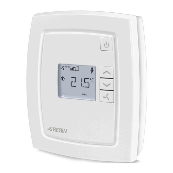
RCF-230TD
Instruction for products with software version
i
1.4. Read this instruction before installation and
wiring of the product.
Consult documentation in all cases where this symbol
is used, in order to find out the nature of the potential
hazards and any actions to be taken.
Room controller for controlling fan-coil units
RCF-230TD is a room controller intended for controlling fan-coil
heaters/coolers and thermal actuators or 3-point actuators.
Installation is directly on the wall or on an electrical connection box.
The controller does not have a communication connection. The fan
can be set to one of three speeds.
RCF-230TD has change-over function and can be used for 2-pipe or
4-pipe systems.
The controller has a function for control of an electric heater.
Technical data
Supply voltage
230 V AC ±10 %, 50/60 Hz
Power consumption
< 3 W
Ambient temperature
0...50°C
Ambient humidity
Max 90 % RH
Storage temperature
-20...+70°C
Built-in temperature sensor NTC type, range 0...50°C
Inputs
Refer to connection illustrations and
table below
Outputs
Relays for fan control, 230 V AC, 3 A
DO4, DO5 for actuators, Triac, 230 V AC,
max. 300 mA (3 A initially)
Terminal blocks
Lift type (maximum cable area 2.1 mm
Protection class
IP20
Pollution degree
2
Overvoltage category
3
Material casing
Polycarbonate, PC
Dimensions
102 x 120 x 29 mm
Installation
Place the controller in a location that has a temperature representative for
the room. A suitable location is approx. 1.6 m above floor level in a place
with unobstructed air circulation.
Depress the locking tab in the upper edge of the controller with a
screwdriver. Carefully turn the screwdriver until the bottom plate and the
electronics unit are slightly separated (see figure 1). Then use the cutout
that becomes visible in the edge of the bottom plate to open the upper
edge completely (see figure 2). Do the same thing in the lower edge of the
controller.
Figure 1
Figure 2
Lift the electronics unit up from the bottom plate. The bottom plate with
terminals has a number of hole combinations. Select suitable holes and
fasten the bottom plate on the wall or connection box, so that the arrows
on the bottom plate point upwards. Do not tighten the screws too hard!
Note: RCF-230TD does not indicate fan breakdown or overheating of the
heating coil. Therefore, all connections must be made externally. An over-
heating protection or similar can be used to disconnect the supply voltage.
RCF-230TD
Disconnection
RCF-230TD should be connected to a switch or circuit breaker in
the building installation. This switch should be in close proximity to
the controller and within easy reach of the operator, and should be
marked as the disconnecting device for the equipment.
)
2
Always use the circuit breaker to disconnect the controller from the
mains supply during maintenance of the fan-coil and actuators.
Settings
Control modes
RCF-230TD can control heating and cooling in sequence or be set to
seasonal switching between heating and cooling (change-over, see
below). Cascade control and min/max limitation of the supply air is
also possible.
Change-over function
RCF-230TD has an input for change-over that automatically resets
the output DO4 to operate with heating or cooling function. When
the controller is used together with a 3-position actuator, output DO5
is also affected by the change-over function in accordance with the
above. A sensor of type PT1000 can be connected to the input and be
mounted so that it senses the temperature on the supply pipe to the
coil.
When the temperature exceeds 28°C, the output function is set to
heating and when the temperature drops below 16°C, the output is
set to cooling. As an alternative, a potential-free contact can be used.
The input function can be set to NO/NC.
To ensure satisfactory functioning when using a sensor, the system
must have continuous primary circuit circulation. When the change-
over function is not used, the input must be left disconnected.
When using an electric heater and the change-over function is set to
heating, the sequence of operation for RCF-230TD will be heating/
heating and DO5 will be activated first.
If a change-over sensor is not connected, the sequence will be heat-
ing/heating. If cooling is to be used in the sequence, parameter 2
(change-over mode) must be changed manually.
When set to cooling, the sequence of operation will be a normal hea-
ting/cooling sequence, where DO4 and DO5 opens according to the
heating and cooling demands.
Operating mode
There are four different operating modes. Switching between these
modes is performed locally.
is shown in the display. Heating and cooling have a
Comfort:
smaller neutral zone. An occupancy detector can be connected to
the DI in order to select between Comfort and Economy. Switching
between Comfort/Economy and Off can also be done via the On/Off
1
Advertisement

Subscribe to Our Youtube Channel
Related Manuals for Regin RCF-230TD


Summary of Contents for Regin RCF-230TD
- Page 1 Control modes Dimensions 102 x 120 x 29 mm RCF-230TD can control heating and cooling in sequence or be set to seasonal switching between heating and cooling (change-over, see Installation below). Cascade control and min/max limitation of the supply air is Place the controller in a location that has a temperature representative for also possible.
- Page 2 1=Active (fan never stops) protection is active or the cool-down function for the electric heater is solid state relay) is to be connected between RCF-230TD and the battery. Deadband at Comfort mode. If the deadband is running, in which case the fan will run in these modes as well).
- Page 3 Released or beta version Both heating and cooling control overheated. Revision Start signal in % of the controller output, heating 20 (5 Display backlight low or cooling, for fan speed 1 when using an Display backlight high electric heater) RCF-230TD...
- Page 4 Fan-coil output 1 Relay, 230 V AC*, 3 A for fan control Fan-coil output 2 Relay, 230 V AC*, 3 A for fan control Fan-coil output 3 Relay, 230 V AC*, 3 A Figure 5: Connection diagram for fan control RCF-230TD...
-
Page 5: Installation
Rumsregulator för styrning av fan-coil-enheter ing with 3-point 20 ms. actuator. Heating/ RCF-230TD är en rumsregulator avsedd att styra fan-coil-värmare/ky- cooling when lare och termiska ställdon eller 3-punktsställdon. Montage sker direkt electrical heater is på vägg eller eldosa. Regulatorn har ej kommunikationsanslutning. - Page 6 Ekonomiläge. En fönsterkontakt kan även anslutas till UI1. Reglerfall Till/Från-knapp RCF-230TD kan styra värme och kyla i sekvens eller ställas till sä- Genom att trycka på Till/Från-knappen växlar RCF-230TD mellan songsvis omställning mellan värme och kyla (change-over, se nedan). Börvärde Frånläge och Komfort-/Ekonomiläge.
- Page 7 Vid användning av elvärmare ska en extern enhet (t.ex. PULSER- Nº Beskrivning Nº Beskrivning ADD eller ett solid state relä) anslutas mellan RCF-230TD och bat- Dödband vid komfortläge. Om dödbandet är 2 K Startsignal i % av regulatorns utstyrning, värme 20 (5 teriet.
- Page 8 Kaskadfaktor mellan rumsregulator och till- 3°C Figur 6: Inkopplingsschema med elvärmare luftsregulator Frysskyddstemperatur för tilluft när begräns- 8°C ning av tilluftstemperatur är aktiv Aktivera begränsning av tilluftstemperatur för: 0 = Värmereglering 1 = Kylreglering Figur 4: Inkopplingsschema 2 = Både värme- och kylreglering RCF-230TD...
- Page 9 4 och 5 Kontakt Digital utgång 5 Digital utgång. 230 V AC, AB Regin, Box 116, 428 22 Kållered för kylsignal el- max 300 mA. Max 2 A under Tel: +46 31 720 02 00, Fax: +46 31 720 02 50 ler stänga med...
-
Page 10: Montage
Um zufriedenstellenden Betrieb mit einem Fühler zu gewährleisten, muss das System über kontinuierliche Zirkulation im Hauptkreis ver- RCF-230TD ist ein Raumregler für die Regelung von Fan-Coils (mit fügen. Bei Nichtverwendung der Umschaltfunktion muss der Eingang Erhitzer/Kühler) und thermischen oder 3-Punkt Stellantrieben. Die offen gelassen werden. - Page 11 Regelungsfunktion für elektrische Erhitzer turfühler oder Digitaleingang der Ventilator in allen Betriebsmodi, außer dem Abschaltbetrieb und RCF-230TD ist mit einer Funktion für die PWM-Regelung von elektri- Betriebsmodus bei aktiviertem DI 1: Fenster (bei aktivierter Schimmelschutzfunktion oder die Abkühl- schen Erhitzern in Sequenz mit einem Warmwasserbereiter ausgestattet, 0=Eco (Präsenzmelder)
- Page 12 Start Ventilatorstufe 2 zung für: 0 = Heizregelung, 1 = Kühlregelung, Stellsignal der Regelung Heizen od. Kühlen in % 2 = Heiz- und Kühlregelung für Start Ventilatorstufe 3 Hysterese für Ein-/Ausschalten der Ventilatorstu- fen (in % des Stellsignals) Anzahl der Ventilatorstufen RCF-230TD...
- Page 13 N-Leiter Fan- schluss (intern mit Klemme Coil/230 V AC 12 verbunden) Abb.7 Anschlussbild mit elektrischem Erhitzer Fan-Coil-Ausgang Relais, 230 V AC*, 3 A 1 für Ventilatorre- gelung Fan-Coil-Ausgang Relais, 230 V AC*, 3 A Abb.5 Anschlussbild 2 für Ventilatorre- gelung RCF-230TD...
- Page 14 Digitaleingang Potenzialfreier Fenster- oder RCF-230TD est doté d’une fonction change-over et peut être utilisé Präsenzkontakt. Einstellbar dans des installations à 2 ou 4 tubes. als NO/NG. Il dispose aussi d’une fonction pour la commande de batterie élec-...
- Page 15 Chauffage/Chauffage. Si le refroidissement doit être utilisé, il parmi : lente, moyenne, rapide ou auto. En mode Auto, la vitesse du Remarque : RCF-230TD n’a pas de fonction pour avertir en cas de faut changer le paramètre 2 (mode change-over) manuellement.
- Page 16 Contrôle manuel du ventilateur Remarque : RCF-230TD n’a pas de fonction pour avertir en cas de Nº Description En appuyant sur le bouton ventilateur, vous pouvez changer la vitesse dysfonctionnement du ventilateur ou de surchauffe de la batterie chaude, Protection anti-moisissure : du ventilateur selon la séquence suivante : IàIIàIIIàAUTO.
- Page 17 4 = Seul le bouton ventilateur est actif 13 K Seuil de mise en route = 22 °C 5 = Boutons marche/arrêt et ventilateur actifs 6 = Flèches vers le haut/bas et bouton « ventila- teur » actifs 7 = Tous les boulons sont actifs RCF-230TD...
- Page 18 (connectée en Fig. 7. Schéma de raccordement avec une batterie électrique 230 V AC interne à la borne 12) Sortie 1 du ven- Relais, 230 V AC*, 3 A tilo-convecteur pour le contrôle du Fig. 5. Schéma de raccordement ventilateur RCF-230TD...
-
Page 19: Port Description
300 mA Max. 2 A Contact du refroidisse- pendant AB Regin, Box 116, 428 22 Kållered, Suède ment ou de la 20 ms. Tél. : +46 31 720 02 00, Fax : +46 31 720 02 50 fermeture avec www.regincontrols.com, info@regin.se...
Need help?
Do you have a question about the RCF-230TD and is the answer not in the manual?
Questions and answers