Advertisement
Quick Links
Unpacking Instructions
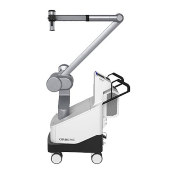
ORBEYE SURGICAL MICROSCOPE
OME-V200
1 Instruction manual
This manual describes the necessary and indispensable information for safe and effective unpacking of the product
(OME-V200). Before unpacking, thoroughly review this manual, understand the instructions given in them and unpacking
the product as instructed in them.
If you have any questions about any information in this manual, contact Olympus.
2 Signal words
CAUTION
NOTE
3 Cautions and notes on unpacking
Strictly observe the following cautions and notes in the unpacking work. Also read and heed the cautions and notes given
in individual chapters.
CAUTION
Always perform the work on a flat floor. Otherwise, the product may topple down or fall from the pallet.
NOTE
• Recommend that you work with two or more people.
• For unpacking, a phillips screwdriver, cutter, nipper is required.
• The side that is described as "R" on the side of the pallet is the rear side, the side indicated as "F" is the front side.
• To unpack the product, clearance of 2 m or more is required on the rear side and clearance of 1 m or more is
required on the front side and both sides of the package.
Be sure to reserve this space before unpacking.
• When disposing of packing materials after unpacking, follow all applicable national and local laws and guidelines.
INSTRUCTIONS
Indicates a potentially hazardous situation which, if not avoided, may result in minor or moderate injury.
It may also be used to alert against unsafe practices or potential equipment damage.
Indicates additional helpful information.
Rear side
("R" is
described)
1 m or more
2 m or more
Front side
("F" is
described)
1 m or more
1 m or
more
Pallet
Figure 1
– 1 –
USA: CAUTION:
Federal law restricts this device to
sale by or on the order of a physician.
Advertisement

Subscribe to Our Youtube Channel
Related Manuals for Olympus OME-V200


Summary of Contents for Olympus OME-V200
- Page 1 1 Instruction manual This manual describes the necessary and indispensable information for safe and effective unpacking of the product (OME-V200). Before unpacking, thoroughly review this manual, understand the instructions given in them and unpacking the product as instructed in them.
- Page 2 4 Unpacking Cut and remove the ester bands (× 3) by the nipper. Ester bands (× 3) Figure 2 CAUTION Be careful not to cut your hand when cutting the ester band. Remove the cap. Figure 3 NOTE The removed cap will later be used as a slope. Cut the tape of (four corners of) the pallet by the cutter.
- Page 3 Remove metallic fasteners (× 16) by phillips screwdriver. Metallic fasteners While holding the sleeves so that the sleeves will not collapse, remove the sleeves (× 2). Sleeve Figure 5 Pull and remove the pads (× 8). Pads Pads Front Rear Figure 6 Remove the BI pad.
- Page 4 Take out the package carton. Package carton Figure 8 While holding the frame so that the frame will not collapse, Frame remove the pipes (× 6). Pipes Figure 9 Remove the frame. Loosen the strap of bag 2, remove bag 2. Bag 1 Bag 2 Strap (Bag2)
- Page 5 Place the air jack between the casters against the caster on the rear side. At this time, confirm that the band of air jack is not removed. Rear Front Band Figure 11 Close the air outlet plug (pink) of the air jack by rotating the plug clockwise.
- Page 6 NOTE Remove stand R by supplying air while using the line (yellow) as a reference. If stand R is hard to remove, feed more air. Stand R Air jack Line (yellow) Figure 14 Remove stand R. Stand R Figure 15 Loosen the air outlet plug (pink) of the air jack by rotating the plug counterclockwise until the air jack can be moved.
- Page 7 Close the air outlet plug (pink) of the air jack by rotating the plug clockwise. Air outlet plug (pink) Figure 17 Place the air jack on the caster on the front side. At this time, confirm that the band of air jack is not removed. Band Figure 18 Remove the cap of the air inlet plug (white) and supply air until stand F can be removed using the pump.
- Page 8 Remove stand F. Stand F Figure 21 Remove stand F and exhaust air by rotating the air outlet plug (pink) counterclockwise until the air jack can be removed. Air outlet plug (pink) Figure 22 CAUTION • When exhausting air, be careful not to have your hand or an object caught by the caster. •...
- Page 9 Place the side with the velcro of the cap to the rear side, fix the cap onto the pallet by attaching velcro so that the line on the cap is hidden. Rear Pallet Line Velcro Figure 25 Holding the movement handles of this instrument firmly. Check the position of the brake pedal, push up it with a foot to unlock the casters.
- Page 10 Check the position of the brake pedal, push it until it hits the back, apply the brake. Brake pedal Figure 28 CAUTION After confirming that this instrument is locked to the floor, and then release your hand from movement handles. Otherwise, this instrument will have momentum and fall over.
- Page 11 NOTE During and after removal of bag 1, be careful not to touch the lens surface on the microscope section. Microscope section Lens surface Figure 31 – 11 –...
- Page 12 Fax: (03)9543-1350 Telephone: (03)9265-5400 Fax: (040)23773-4656 Telephone: (040)23773-0 5301 Blue Lagoon Drive, Suite 290 Miami, FL 33126-2097, U.S.A. Olympus Tower 9F, 446, Bongeunsa-ro, Gangnam-gu, Seoul, Korea 135-509 KeyMed House, Stock Road, Southend-on-Sea, Essex SS2 5QH, United Kingdom Fax: (305)261-4421 Telephone: (305)266-2332...
Need help?
Do you have a question about the OME-V200 and is the answer not in the manual?
Questions and answers