Table of Contents
Advertisement
Advertisement
Chapters
Table of Contents
Troubleshooting

Subscribe to Our Youtube Channel
Related Manuals for Olympus UHI-2


Summary of Contents for Olympus UHI-2
- Page 1 MAINTENANCE MANUAL UHI-2...
- Page 2 Repairs of this product require high-grade special knowledge and technique. We recommend to contact the Olympus agent in your country when product goes out of order. For remodeling or repairs to be done by the agent or person not authorized...
-
Page 3: Table Of Contents
CONTENTS CONTENTS 1. SPECIFICATIONS 2. TROUBLESHOOTING 3. DISASSEMBLING AND ASSEMBLING PROCEDURE 4. EXPLODED PARTS DIAGRAM 5. PARTS LIST... -
Page 4: Specifications
Wall piping adapter: MAJ-626, MAJ-627 Pneumatic tube: MAJ-397, MAJ-590 Suction tube: MAJ-591 Olympus pneumatic needle, trocar Pneumatic needle, trocar: Exhaust unit: MAJ-529 Supply pressure display The supply pressure is displayed as a bar graph in red and green on the front panel. - Page 5 SPECIFICATIONS Item Specification Control When the abdominal pressure reaches the set value, gas feeding is stopped. When the abdominal pressure is lowered 1 mmHg below the set value, gas feeding is stopped. Display method (1) Abdominal pressure display bar graph The number of lighting is determined by the ratio of the abdominal pressure to the set value.
- Page 6 SPECIFICATIONS Item Specification Control (1) When there is a large difference between the abdominal pressure and set value, gas is fed at the set flow rate. (2) As the abdominal pressure is coming close to the set value, lower the flow rate gradually. (3) When the abdominal pressure reaches the set value, stop feeding gas.
- Page 7 SPECIFICATIONS Item Specification Operation ON/OFF (1) Each time the foot switch is stepped, gas feeding and suction interlock to maintain the abdominal pressure at the set value. When the foot switch is released, the smoke evacuation is stopped. (2) Operation by communication. (3) Smoke evacuation by the smoke evacuation unit Gas feed rate at smoke Gas is fed at the set flow rate.
- Page 8 SPECIFICATIONS Item Specification Operating environment Ambient temperature: 10 to 40 C Humidity: 30 to 85% Atmospheric pressure: 700 to 1060 hpa Operating atmosphere: Don't operate in inflammable atmosphere. Applicable gas: Medial CO Medical gas piping Supply pressure: 4 ±0.5 kgf/cm (JIS) Flow rate: 40 L/min or more (0°C, 1 atmospheric...
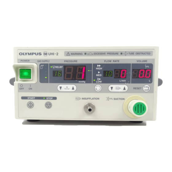
- Page 9 SPECIFICATIONS 3. Nomenclature 1-1 Front panel 18. Warning Lamp for Excessive Pressure 15. Set Flow Rate Indicators 12. Bar Graph for Abdominal Pressure 11. Abdominal pressure 19. Warning Lamp for Tube Obstruction indicators 16. Bar Graph for 9. Lamp for Relief Mode Flow Rate 8.
- Page 10 SPECIFICATIONS 2-1 Rear panel 3. FOOT SWITCH Connector 1. AC Inlet 2. Circuit Breakers 5. CO Gas Inlet 6. SYSTEM connector 4. Equipotential Terminal AC Inlet Circuit Breakers FOOT SWITCH Connector Equipotential Terminal Gas Inlet SYSTEM connector...
- Page 11 Hose For Medical Gas Pipeline Hose For Cylinder (MAJ-622/623/624)(Optional) Foot Switch (MH~3l7)(Optional) CO2 CYLINDER These items are contained HAJ-590 or MH-397 High Flow Insufflation Unit{UHI-2) Insufflation Tube (MW-590) Disposable Filter Filter Connecting Tube Luer-lock Connector These items are contained HAJ-591 Tube...
- Page 12 SPECIFICATIONS 5. Using Conditions (1) Use the unit in a medical facility under the direction of a doctor. (2) Don't use the unit in inflammable atmosphere. (3) Ground the casing for safety. (4) Use a medical power receptacle as a power supply. (5) Use medical CO gas, the exclusive high pressure hose and wall piping adapter.
-
Page 13: Troubleshooting
TROUBLESHOOTING 2. TROUBLESHOOTING Troubleshooting Power is not supplied. (Power supply check) 1-2 The indicator is not lit. The panel switch is not accepted. (Error check Gas is not fed. (Gas supply check) Gas is not supplied. The indicator is lit. (Error check 1-5 Gas is not fed. -
Page 14: Troubleshooting
TROUBLESHOOTING 1. Troubleshooting 1-1 Power is not supplied. (Check the power supply procedure.) Check the power supply procedure. Turn on the power switch. Does the power indicator light? The cord is not connected to the Check the inlet plug. unit, or is broken. Wrong connection of the cord Lights? Defective breaker... -
Page 15: The Indicator Is Not Lit. The Panel Switch Is Not Accepted
TROUBLESHOOTING 1-2 The indicator is not lit. The panel switch is not accepted. (Error check Error check Check the power supply procedure. Does the panel work? Check the connection of all harness. Especially, the connection of the Check the connection. flat cable between UPUH25U and panel sheet. -
Page 16: Gas Is Not Fed. (Gas Supply Check)
TROUBLESHOOTING 1-3 Gas is not fed. (Gas supply check) Gas supply check Press the gas feed switch. Does the red LED of the supply pressure display bar graph light? Is gas fed? Check the high pressure hose or the wall piping adpter. Check the connection. -
Page 17: Gas Is Not Supplied. The Indicator Is Lit
TROUBLESHOOTING 1-4 Gas is not supplied. The indicator is lit. (Error check Error check Gas supply check Turn on the gas feed start switch. Is gas fed? Check the harness. Connected? Valves) Is gas fed? Broken? Dent? Check the internal Dioine. Obstructed? Disconnected? Is gas fed? -
Page 18: Gas Is Not Fed. (Electric-Pneumatic Ratio Valve And Solenoid Valve Check)
TROUBLESHOOTING 1-5 Gas is not fed. (Electric-pneumatic ratio valve and solenoid valve check) Electric-pneumatic ratio valve and solenoid valve check 1. Start up while pressing the flow rate UP switch. Set the check mode 1. 2. Select the gas feed mode "Low". 3. -
Page 19: Noise Is Generated In The Unit. (Noise Check)
TROUBLESHOOTING 1-6 Noise is generated in the unit. (Noise check) Noise check Is noise generated during halt of operation? Gas leaks in the high pressure part. Looseness? Check the joints of each pipe. Hole? Is noise generated during gas feeding? Primary pressure reducer safety valve? Replace the primary... -
Page 20: Smoke Is Not Evacuated. (Smoke Evacuation Check)
TROUBLESHOOTING 1-7 Smoke is not evacuated. (Smoke evacuation check) Smoke evacuation check Check the connection with the suction Is smoke evacuated? Replace the foot switch (MH-317). Is smoke evacuated? Does the LED (DS4) on the UPUH15U Check the pinch valve lights? operation. -
Page 21: Relief Fails. (Relief Check)
TROUBLESHOOTING 1-8 Relief fails. (Relief check) Relief mode does not work. Check that the relief mode indicator is lighting. Check the relief mode. Relieved? Does the LED DS3 flicker when the set pressure value is +5 mmHg or higher? Defective UPUH15U Defective solenoid valve Replace the UPUH15U. -
Page 22: Disassembling And Assembling Procedure
DISASSEMBLING/ASSEMBLING PROCEDURE 3. DISASSEMBLING AND ASSEMBLING PROCEDURE 1 Precautions on Disassembling/Assembling 1-1 Disassembling 1-2 Assembling 2 Jigs and Tools 3 Disassembling/Assembling Procedure 3-1 Top cover 3-2 Front panel unit 3-3 Rear panel unit 3-4 Power supply unit 3-5 K-connector unit 3-6 1st pressure reducing unit 3-7 Electric pneumatic unit 3-8 Manifold unit... -
Page 23: Precautions On Disassembling/Assembling
DISASSEMBLING/ASSEMBLING PROCEDURE 1. Precautions on Disassembling/Assembling 1-1 Disassembling • Replace the parts and wires to the original positions. • To ensure electrical safety and satisfy the electrical standard, be sure to assemble the following parts to the original state. Insulating materials such as insulating tube and mylar sheet Cables clamped no to approached to the parts that generate heat and high voltage Cover screws using a toothed lock washer to suppress a radiation noise •... -
Page 24: Disassembling/Assembling Procedure
DISASSEMBLING/ASSEMBLING PROCEDURE Disassembling/Assembling Procedure 3-1 Top cover Disassembling Remove the screws HCBK4x8SA (9 pcs.) and CBK4x6SA (1 pc.) which secure the top cover. CBK4x6SA Lift and remove the top cover. Philips screwdriver No. 2 Assembling Mount the top cover on the main body. Secure the top cover to the main body with the screws HCBK4x8SA (9 pcs.) and CBK4x6SA (1 pc.). -
Page 25: Rear Panel Unit
DISASSEMBLING/ASSEMBLING PROCEDURE 3-3 Rear panel unit Disassembling Remove the harness from the rear panel unit. 2. Remove the screw HCBK4x8SA (3 pcs.) which secure the rear panel. 3. Remove the rear panel unit from the main body. Philips screwdriver No. 2 Assembling 1. -
Page 26: K-Connector Unit
DISASSEMBLING/ASSEMBLING PROCEDURE 3-5 K-connector unit Disassembling Remove the S-ring from the K-connector Connect to the UPUH15U J2. with a spanner. Remove the screw CCUK4x6SZ (4 pcs.) CCUK4x6SZ S-ring which secure the K-connector unit. Assembling Secure the K-connector unit with the screw CCUK4x6SZ (4 pcs.). -
Page 27: Electric Pneumatic Unit
DISASSEMBLING/ASSEMBLING PROCEDURE 3-7 Electric pneumatic unit Disassembling Remove the tube and harness from the electric pneumatic unit. Connect to the 1st pressure reducing Remove the screw CCUK4x6SZ (4 pcs.) unit. which secure the electric pneumatic unit. Connect to the manifold unit. Philips screwdriver No. -
Page 28: Front Panel Unit
Downward, Pressure sensor pressure reducing unit Electric pneumatic unit Manifold unit K-connector unit UHI-2 Piping Diagram 3-9 Front panel unit Disassembling Remove the screw HCBK3x6SA (6 pcs.) which secure the UPUH15U. UPUH15U HCBK3x6SA Remove the claw of the spacer which secures the UPUH15U. -
Page 29: Exploded Parts Diagram
EXPLODED PARTS DIAGRAM EXPLODED PARTS DIAGRAM EXPLODED PARTS DIAGRAM FR.1107 MODEL UNIT FIG.1/7 UHI-2 FRONT PANEL... - Page 30 EXPLODED PARTS DIAGRAM EXPLODED PARTS DIAGRAM MODEL UNIT FR.1107 UHI-2 TOP COVER CHASSIS FIG.2/7...
- Page 31 EXPLODED PARTS DIAGRAM EXPLODED PARTS DIAGRAM MODEL UNIT FR.1107 UHI-2 REAR PANEL FIG.3/7...
- Page 32 EXPLODED PARTS DIAGRAM EXPLODED PARTS DIAGRAM MODEL UNIT FR.1107 UHI-2 FLOW SENSOR FIG.4/7...
- Page 33 EXPLODED PARTS DIAGRAM EXPLODED PARTS DIAGRAM FR.1107 MODEL UNIT UHI-2 REGULATOR FIG.5/7...
- Page 34 EXPLODED PARTS DIAGRAM EXPLODED PARTS DIAGRAM MODEL UNIT FR.1107 FIG.6/7 UHI-2 TUBE...
- Page 35 EXPLODED PARTS DIAGRAM EXPLODED PARTS DIAGRAM MODEL UNIT FR No.1107 CABLE UHI-2 FIG.7/7...
-
Page 36: Parts List
PARTS LIST 5. PARTS LIST PARTS No. INDEX PARTS NAME SPECIFICATION REMARK DB085200 3-B2 BLEAKER T11-2111A BB-318 DF053000 3-A2 LINE FILTER FN9223 DH227100 3-A1 POAG-S6/15 TERMINAL DK1 43600 3-A1 METAL FITTINGS JAE D20418-J DO077100 3-D2 CORD HOLDER DO1 35700 3-A2 EDGING DO151700 1-B2... - Page 37 PARTS LIST PARTS No. INDEX PARTS NAME SPECIFICATION REMARK GJ439900 7-B4 CABLE EQUIPOTENTIAL GND GJ440000 CABLE 7-A3 BLEAKER-POWER SW GJ440100 7-B4 CABLE POWER SW-POWER SUPPLY GJ440300 7-D3 CABLE SYSTEM CONNECTOR GJ440400 7-C3 CABLE FOOT SW CONNECTOR GJ450100 1-C1 MAIN BORAD UNIT GJ450400 5-B1 K-CONECTOR UNIT...
- Page 38 OLYMPUS OPTICAL CO..LTD. San-Ei Building,22-2,Nishi Shinjuku 1-chome,Shinjuku-ku,Tokyo,Japan OLYMPUS OPTICAL CO.,(EUROPA) GMBH (Premises/Goods delivery)Wendenstrasse 14-16,0-20097 Hamburg.Genmany (Letters:Postfach 104908,0-20034 Hamburg.Germany) OLYMPUS WINTER & IBE GMBH Kuehnstrasse 61,d-22045 Hanburg, Germany OLYMPUS AMERICA INC. Two corporate Center Drive Melville,N.Y. KEYMAD (MEDICAL & INSTRUMENT EQUIPMENT)LTD.
Need help?
Do you have a question about the UHI-2 and is the answer not in the manual?
Questions and answers