
Related Manuals for Olympus OTV-SI


Summary of Contents for Olympus OTV-SI
- Page 1 VISY218 INSTRUCTIONS VIDEO SYSTEM OTV-SI USA: CAUTION: Federal law restricts this device to sale by or on the order of a physician.
- Page 2 VISY218...
-
Page 3: Table Of Contents
Connection of the endoscope ............Connection to the color video printer (OEP-3/OEP-not available in some countries)........ Connection to the video tape recorder..........Connection to a wall mains outlet ........... Attachment of the water container (MD-431, type B only) ....VIDEO SYSTEM OTV-SI... - Page 4 5.16 Recording with the video tape recorder .......... 5.17 Rotated image................. 5.18 Air/water feed (type B only)............. 5.19 After use..................Chapter 6 Care, Storage and Disposal ........133 Care ....................Lamp replacement ................Storage ................... Disposal ..................VIDEO SYSTEM OTV-SI...
- Page 5 VISY218 Contents Chapter 7 Troubleshooting ............138 Troubleshooting guide ..............Returning the instrument for repair ..........Appendix ..................143 System chart .................... Operating environment................Transportation and storage environment ..........Specifications ................... VIDEO SYSTEM OTV-SI...
- Page 6 VISY218 Contents VIDEO SYSTEM OTV-SI...
-
Page 7: Labels And Symbols
VISY218 Labels and Symbols Labels and Symbols Safety-related labels and symbols are attached to the instrument at the locations shown below. If labels or symbols are missing or illegible, contact Olympus. Rear side Potential equalization terminal CSA marking Fuse rating label... - Page 8 VISY218 Labels and Symbols Electrical rating label Fuse rating label Lamp rating plate Back cover of this instruction manual Manufacturer Authorized representative in the European Community VIDEO SYSTEM OTV-SI...
-
Page 9: Important Information - Please Read Before Use
Important Information — Please Read Before Use Intended use This instrument has been designed to be used with an Olympus videoscope, camera head, rigid endoscope or fiberscope with a rigid endoscope eyepiece, video monitor, endo-therapy accessories and other ancillary equipment for endoscopic observation, diagnosis and treatment. -
Page 10: User Qualifications
Instrument compatibility Refer to the “System chart” in the Appendix to confirm that this instrument is compatible with the ancillary equipment being used. Using incompatible equipment can result in patient injury and/or equipment damage. VIDEO SYSTEM OTV-SI... -
Page 11: Repair And Modification
Some problems that appear to be malfunctions may be correctable by referring to Chapter 7, “Troubleshooting”. If the problem cannot be resolved using the information in Chapter 7, contact Olympus. Signal words The following signal words are used throughout this manual: Indicates an imminently hazardous situation which, if not avoided, will result in death or serious injury. -
Page 12: Dangers, Warnings And Notes
Keep liquids away from all electrical equipment. If liquid enters the unit, stop the operation of the equipment immediately and contact Olympus. Do not prepare, inspect or use this equipment with wet hands. - Page 13 If you continue to use the endoscope in such a condition, the temperature at the distal end may rise and cause mucosal burns. It may also cause patient and/or operator injury. VIDEO SYSTEM OTV-SI...
- Page 14 Be sure to observe the following points. Otherwise, a failure in an electrical contact may result in malfunction. Do not touch the electrical contacts in the video connector socket of this instrument. Do not apply excessive force to the connectors. VIDEO SYSTEM OTV-SI...
-
Page 15: Cardiac Applications
• The OLYMPUS light guide cable and camera head listed in the “System chart” (TYPE CF APPLIED PART) in the Appendix as suitable for cardiac applications bear a mark. -
Page 16: Chapter 1 Checking The Package Contents
Match all items in the package with the components shown below. Inspect each item for damage. If the instrument is damaged, a component is missing or you have any questions, do not use the instrument; immediately contact Olympus. Type A... - Page 17 VISY218 Chapter 1 Checking the Package Contents Type B Video system (OTV-SI) SI spare fuse (MAJ-1242, 2 pcs) Y/C cable (MH-985) BNC cable (B) (MB-677) Power cord Water container (MD-431) Instruction manual VIDEO SYSTEM OTV-SI...
-
Page 18: Chapter 2 Nomenclature And Functions
Video connector socket plug Automatic control White balance Automatic/manual Manual control Brightness Air feed Down Lamp Rear panel Potential equalization Serial number Caution, Alternating current refer to instructions. Fuse Side panel Caution, Caution-hot refer to instructions. VIDEO SYSTEM OTV-SI... -
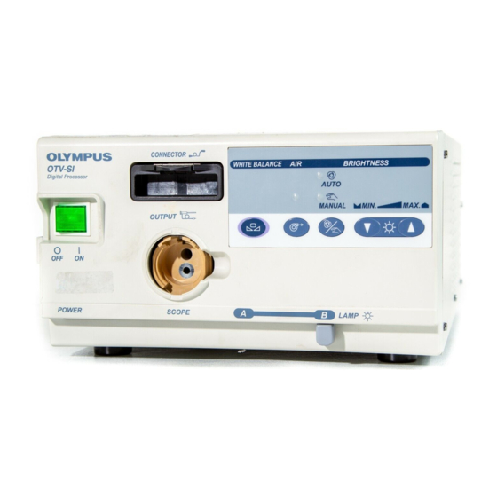
Page 19: Front Panel
Type A 1. Power switch 4. White balance switch 2. Video connector socket 5. Auto indicator 7. Auto/Manual 6. Manual indicator 3. Output connector brightness selector 10. Unlocking lever 8. Brightness control switches 9. Lamp selection lever VIDEO SYSTEM OTV-SI... - Page 20 5. Auto indicator 7. Auto/Manual 6. Manual indicator 3. Output connector brightness selector 10. Unlocking lever 9. Lamp selection lever 8. Brightness control switches 12. Air feed indicator 11. Air feed switch (type B only) (type B only) VIDEO SYSTEM OTV-SI...
- Page 21 This lever is pushed down to disconnect the video plug of the videoscope or camera head. 11. Air feed switch (type B only) This switch is pressed to start or stop air feeding. 12. Air feed indicator (type B only) This indicator lights when air is feeding. VIDEO SYSTEM OTV-SI...
-
Page 22: Rear Panel
1. Video output terminals 4. Hard copy terminal (Y/C terminal) 5. VTR remote terminal 2. Video output terminal (BNC terminal) 6. Keyboard terminal 3. System terminal 7. Fuse box 8. AC power inlet 9. Potential equalization terminal Ventilation grilles VIDEO SYSTEM OTV-SI... - Page 23 2. Video output terminal (BNC terminal) The composite video signal is transmitted via this terminal. 3. System terminal This terminal is used to service this instrument by OLYMPUS. 4. Hard copy terminal Communication signals for the color video printer (OEP-3/OEP) are transmitted via this terminal.
-
Page 24: Side Panel
1. Latch 3. Lamp access cover 1. Latch Pull up to open the lamp access cover. 2. Water container holder (type B only) Hang the water container here. 3. Lamp access cover Open to replace the lamp. VIDEO SYSTEM OTV-SI... -
Page 25: Ancillary Equipment
Water container (MD-431, type B only) The water container is used to feed air and water to the videoscope. SI spare fuse (MAJ-1242) The spare fuse is used to replace the original fuse in this instrument if it blows. VIDEO SYSTEM OTV-SI... -
Page 26: Keyboard (Optional)
VISY218 Chapter 2 Nomenclature and Functions Keyboard (optional) If you need a keyboard, contact Olympus. Use only the Olympus keyboard for OTV-S7V (MAJ-1124). 1. “Esc” key 6. “F5” key 2. “F1” key 7. “F6” key 3. “F2” key 13. “Delete” key 8. - Page 27 8. “F7” key This key is pressed to electrically magnify the image. 9. “F8” key This key is pressed to display the menu for saving or loading user and default settings. 10. “F9” – “F12” keys Not used. VIDEO SYSTEM OTV-SI...
- Page 28 These keys are pressed to enter uppercase characters. Press this key and the “Shift” key simultaneously to enter lowercase characters. 20. “Tab” key This key is pressed to move to the next item in the character input mode. VIDEO SYSTEM OTV-SI...
-
Page 29: Menu Actions
This number refers to the patient data entry. Select a number to NO. [ 1] save or load patient data. The numbers 0 – 9 are available. Store the patient data. STORE Hide the patient data, date and time. HIDE Show the patient data, date and time. SHOW VIDEO SYSTEM OTV-SI... - Page 30 Select the day of the month (1 – 31). D[ 1] Select the hour of the day (0 – 23). H[ 13] Select the minute (00 – 59). M[ 07] Select the second (00 – 59). S[ 02] Save the date and time. VIDEO SYSTEM OTV-SI...
-
Page 31: Chapter 3 Installation And Connection
Prepare this instrument, the compatible ancillary equipment (shown in the “System chart” in the Appendix) and other equipment to be used with this instrument before each use and refer to the instruction manual for each piece of equipment. VIDEO SYSTEM OTV-SI... -
Page 32: Installation
Place this instrument on a stable, level surface. Failure to do so may cause the instrument to fall. • If the compact trolley (TC-C2) is not used, confirm that this instrument does not exceed the allowed maximum load for the installation site. VIDEO SYSTEM OTV-SI... - Page 33 Place the instrument on the trolley’s shelf, making sure that it is level. Installation in another location Place the instrument on a stable, level surface. Do not obstruct the ventilation grilles with ancillary equipment, etc. VIDEO SYSTEM OTV-SI...
-
Page 34: Connection To The Video Monitor
The position of the video input/output connectors is variable depending on the model of the video monitor. When using a video monitor other than the OEV143/203, confirm the positions of the VIDEO and Y/C input connectors by referring to its instruction manual. VIDEO SYSTEM OTV-SI... - Page 35 VISY218 Chapter 3 Installation and Connection OEV143/203 rear terminal Y/C cable (MH-985) Video system (OTV-SI) Figure 3.2 VIDEO SYSTEM OTV-SI...
-
Page 36: Connection To The Keyboard (Optional)
• Do not pull the keyboard cable with excessive force once it has been connected to this instrument. Doing so may result in connection failure or the inability of the OTV-SI to accept input from the keyboard. • Keep the HF equipment and ancillary cords as far away as possible from the keyboard and its cord. - Page 37 VISY218 Chapter 3 Installation and Connection Video system (OTV-SI) Keyboard cable Keyboard (MAJ-1124) Figure 3.3 VIDEO SYSTEM OTV-SI...
-
Page 38: Connection Of The Endoscope
OTV-SI. Wet equipment could cause the image to flicker or disappear. Do not connect or disconnect the video plug while the OTV-SI is ON. Doing so may damage the electrical circuits inside the camera head. Connecting Confirm that the video plug and its electrical contacts are dry (see Figure 3.4). - Page 39 Video connector socket UP mark Video plug Figure 3.5 Disconnecting Turn this instrument OFF. Press the video connector socket’s unlocking lever and pull the video plug straight out (see Figure 3.6). Unlocking lever Video plug Figure 3.6 VIDEO SYSTEM OTV-SI...
- Page 40 If the endoscope is wet (after disinfection, for example), dry it according to the directions given in the endoscope’s operation or reprocessing manual before connecting it to this instrument. Otherwise, equipment damage and/or improper illumination can result. VIDEO SYSTEM OTV-SI...
- Page 41 Insert the light guide plug into the output connector on the front panel of this instrument until it stops (see Figure 3.8). Insert the light guide plug first. Then insert the video plug. It is easy to connect the endoscope without torsion of the cable. VIDEO SYSTEM OTV-SI...
-
Page 42: Connection To The Color Video Printer (Oep-3/Oep-Not Available In Some Countries)
Output connector Figure 3.8 Connection to the color video printer (OEP-3/OEP-not available in some countries) Turn this instrument and the OEP-3/OEP OFF. Connect the cables to this instrument and the OEP-3 or OEP as shown in Figure 3.9. VIDEO SYSTEM OTV-SI... - Page 43 Chapter 3 Installation and Connection Video monitor BNC cable (B) (MB-677) Y/C cable (MH-985) INPUT S-VIDEO terminal Remote terminal Color video printer (OEP-3/OEP) OUTPUT S-VIDEO terminal OEP cable (MH-987) Y/C cable (MH-985) To wall mains outlet Video system (OTV-SI) Figure 3.9 VIDEO SYSTEM OTV-SI...
-
Page 44: Connection To The Video Tape Recorder
Connect the isolation transformer’s power cord to a wall mains outlet. When using the SVO-9500MD, connect the VTR remote cable and Y/C cable to the video tape recorder as shown in Figure 3.10. The VTR remote control function is only available when using the SVO-9500MD VTR. VIDEO SYSTEM OTV-SI... - Page 45 Chapter 3 Installation and Connection Y/C cable (MH-985) SVO-9500MD Input Output Rear panel Front panel REMOTE 2 S VIDEO IN S VIDEO OUT VTR remote cable (MAJ-438) To video monitor BNC cable (B) (MB-677) Video system (OTV-SI) Figure 3.10 VIDEO SYSTEM OTV-SI...
-
Page 46: Connection To A Wall Mains Outlet
• Never use a table tap. Always connect the power cord directly to a wall mains outlet. Connecting to a table tap can result in fire. VIDEO SYSTEM OTV-SI... - Page 47 Color video monitor OEV 143, OEV 203 Color video printer OEP, OEP-3 The following ancillary equipment must be connected via an isolation transformer (see Figure 3.12). VTR SVO-9500MD Video printers other than OEP-3/OEP Video monitors other than OEV series VIDEO SYSTEM OTV-SI...
- Page 48 Chapter 3 Installation and Connection Direct connection to a wall mains outlet: OTV-SI Color video monitor (OEV143/203) Color video printer (OEP-3/OEP) Wall mains outlet Connection via an isolation transformer: Monitor (non-Olympus) Isolation transformer Video printer (MB-631) (non-Olympus) Figure 3.12 VIDEO SYSTEM OTV-SI...
-
Page 49: Attachment Of The Water Container (Md-431, Type B Only)
Attachment of the water container (MD-431, type B only) Prepare the water container (MD-431) according to the instructions given in its instruction manual. Attach the water container to the water container holder (see Figure 3.13). Figure 3.13 VIDEO SYSTEM OTV-SI... -
Page 50: Chapter 4 Inspection
Should the slightest irregularity be suspected, do not use the instrument and see Chapter 7, “Troubleshooting”. If the irregularity is still suspected after consulting Chapter 7, contact Olympus. Damage or irregularity may compromise patient or operator safety and may result in more severe equipment damage. - Page 51 If the power fails to come on after replacing the fuses, immediately turn this instrument OFF. Remove the power cord from the wall mains outlet and contact Olympus. Equipment damage or malfunction may have occurred and fire or an electric shock can result.
-
Page 52: Illumination Inspection
VISY218 Chapter 4 Inspection Even if only one fuse has blown, always replace both of them (see Figure 4.2). If neither fuse has blown, contact Olympus. Fuse box Fuse Figure 4.2 Insert the fuse box into this instrument until it clicks into position. -
Page 53: Inspection Of The Display On The Monitor
Joggle the camera cable and confirm that the endoscopic image is free from irregularities such as momentary disappearing or flickering. Confirm that the date and time are correct. If the date and time are incorrect, adjust them as described in Section 5.3, “Clock adjustment”. VIDEO SYSTEM OTV-SI... -
Page 54: Inspection Of The Freeze Function
Refer to Section 5.10, “Freeze”. Confirm that freeze and live images are displayed properly on the video monitor. Inspection of the release function Refer to Section 5.15, “Photography with the color video printer (OEP-3/OEP-not available in some countries)”. Confirm that a picture can be taken. VIDEO SYSTEM OTV-SI... -
Page 55: Inspection Of The Manual Brightness Adjustment
Confirm that the brightness of the image on the video monitor remains constant. Inspection of the air/water feed (type B only) Refer to Section 5.18, “Air/water feed (type B only)”, “Air/water feed”. Confirm that air and water can be fed normally. VIDEO SYSTEM OTV-SI... -
Page 56: Chapter 5 Operation
If the endoscopic image disappears or the image freezes and cannot be restored : Turn the OTV-SI OFF. Then turn it back ON again. For ancillary equipment used in conjunction with the OTV-SI, also turn the power OFF and then ON again as directed in their respective instruction manuals. - Page 57 If the lamp burns out during a procedure, move the lamp selection lever to select the other lamp (lamp B or A) and continue the operation. Replace the lamp after completing the procedure following the instructions given in Section 6.2, “Lamp replacement”. VIDEO SYSTEM OTV-SI...
-
Page 58: Turning The Power On
Turn the power for each piece of equipment ON as described in their instruction manuals. Turn ON the OTV-SI Push the instrument’s power switch to turn the video system ON (see Figure 5.1). The power switch lamp will light in green. - Page 59 Figure 5.2) depends upon the number of remote control switches on the videoscope or camera head. For example, when the OTV-S7H-N is connected, only “SW1” and “SW2” are displayed on the video monitor. (Refer to Section 5.9, “Remote control switches”) VIDEO SYSTEM OTV-SI...
-
Page 60: Basic Menu Operation
“execution” or for “selection”, the “F1”, “Enter”, “ ”, “ ”, “” or “” key on the keyboard to display the menu. The currently selected menu is highlighted with a white background (see Figure 5.3). Selected menu Figure 5.3 VIDEO SYSTEM OTV-SI... - Page 61 Select “NEXT” and press the remote control switch for execution, the “Enter” or “ ” key on the keyboard to display the next menu bar shown in Figure 5.4. Pressing the “ ” key on the keyboard displays the previous menu bar. Figure 5.4 VIDEO SYSTEM OTV-SI...
- Page 62 ([ ]) changes the symbol, characters or figures inside the brackets. When the menu is displayed select and execute “EXIT” to exit the menu. The menu can also be exited by pressing the “Esc” key on the keyboard (refer to Section 2.7, “Menu actions”). VIDEO SYSTEM OTV-SI...
-
Page 63: Clock Adjustment
“F1”, “Enter”, “ ”, “ ”, “” or “” key on the keyboard to display the menu bar shown in Figure 5.6. Press the remote control switch for selection, the “” or “” key on the keyboard and select “NEXT” (see Figure 5.6). Figure 5.6 VIDEO SYSTEM OTV-SI... - Page 64 “Enter” or “ ” key on the keyboard four times to display the menu bar shown in Figure 5.7. Figure 5.7 Press the remote control switch for selection, the “” or “” key on the keyboard and select “CONFG.” (see Figure 5.8). Figure 5.8 VIDEO SYSTEM OTV-SI...
- Page 65 Press the remote control switch for selection, the “” or “” key on the keyboard to select the menu item to be set (for example, to set or change the date, select “DATE”) (see Figure 5.10). Figure 5.10 VIDEO SYSTEM OTV-SI...
- Page 66 “Y [ ]” sets the year, “M [ ]” sets the month and “D [ ]” sets the day. For example, to change the month, select “M [04]” (see Figure 5.12). VIDEO SYSTEM OTV-SI...
- Page 67 M [04] refers to the month April. Repeat Steps 8. and 9. to change the year and date. Then press the remote control switch for selection, the “” or “” key on the keyboard to select “SET” (see Figure 5.13). Figure 5.13 VIDEO SYSTEM OTV-SI...
- Page 68 • The set date and time are retained when the video system is turned OFF and turned ON again. • The accuracy of the clock built into the OTV-SI is accurate to within 30 seconds each month. VIDEO SYSTEM OTV-SI...
- Page 69 Select “YMD”, then press the remote control switch for execution, the “Enter”, “ ” or “ ” key on the keyboard to set the display format. The following date format can be chosen: “YMD” : Year/Month/Day “MDY” : Month/Day/Year “DMY” : Day/Month/Year Figure 5.15 VIDEO SYSTEM OTV-SI...
-
Page 70: Adjusting The Video Monitor
“NEXT” (see Figure 5.16). Figure 5.16 Press the remote control switch for execution, the “Enter” or “ ” key on the keyboard two times to display the menu bar shown in Figure 5.17. VIDEO SYSTEM OTV-SI... - Page 71 VISY218 Chapter 5 Operation Figure 5.17 Press the remote control switch for selection, the “” or “” key on the keyboard and select “C.BAR” (see Figure 5.18). Figure 5.18 VIDEO SYSTEM OTV-SI...
- Page 72 “SCOPE” is highlighted and press the remote control switch for execution, the “Enter”, “ ”, “ ”, “Esc”, “F3”, “F5”, “F6”, “F7” or “F9” through “F12” key on the keyboard so that the color-bar image disappears. VIDEO SYSTEM OTV-SI...
-
Page 73: Color Adjustment
Figure 5.17 on page 65. Press the remote control switch for selection, the “” or “” key on the keyboard and select “W/B” (White balance) (see Figure 5.22). VIDEO SYSTEM OTV-SI... - Page 74 “Shift” key on the keyboard simultaneously. Make sure that the distal end of the endoscope is not exposed to strong extraneous light. When the automatic white balance adjustment is complete, the display shown in Figure 5.23 appears on the video monitor. VIDEO SYSTEM OTV-SI...
- Page 75 “Color tone level (red/blue) adjustment” on page 77. Figure 5.24 If the color is not satisfactory after performing the white balance, refer to “Hue level adjustment” on page 71 or “Chroma level adjustment” on page 74 to adjust the color tone manually. VIDEO SYSTEM OTV-SI...
- Page 76 If the color on the video monitor is not adjusted properly, white will not appear on the video monitor, even if white balance has been performed. Adjust the PHASE and CHROMA knobs on the video monitor and refer to Section 5.4, “Adjusting the video monitor”. VIDEO SYSTEM OTV-SI...
- Page 77 Press the remote control switch for execution, “Enter” or “ ” key on the keyboard four times to display the menu shown in Figure 5.7 on page 58. Press the remote control switch for selection, “” or “” key on the keyboard and select “CONFG.” (see Figure 5.25). Figure 5.25 VIDEO SYSTEM OTV-SI...
- Page 78 Press the remote control switch for execution, “Enter” or “ ” key on the keyboard to display the menu shown in Figure 5.26. Figure 5.26 When using camera heads OTV-S7H-1D-F08E/L08E /D-L08E, the “ASGN.” menu option displayed in Figures 5.26 and 5.27 may not be displayed on the monitor. VIDEO SYSTEM OTV-SI...
- Page 79 “HUE” (see Figure 5.27). Figure 5.27 Press the remote control switch for execution, “Enter”, “ ” or “ ” key on the keyboard to display the menu shown in Figure 5.28. Figure 5.28 VIDEO SYSTEM OTV-SI...
- Page 80 Figure 5.7 on page 58. Press the remote control switch for selection, “” or “” key on the keyboard and select “CONFG.” (see Figure 5.25 on page 71). VIDEO SYSTEM OTV-SI...
- Page 81 Press the remote control switch for execution, “Enter” or “ ” key on the keyboard two times to display the menu shown in Figure 5.29. Figure 5.29 Press the remote control switch for selection, “” or “” key on the keyboard and select “CHROM” (see Figure 5.30). Figure 5.30 VIDEO SYSTEM OTV-SI...
- Page 82 If the chroma level is at the midpoint, the display shows “0”. The chroma level can be adjusted in 8 steps from the • midpoint. • When the chroma level is at the maximum or minimum, the display shows “+” or “”. VIDEO SYSTEM OTV-SI...
- Page 83 “CONFG.” (see Figure 5.25 on page 71). Press the remote control switch for execution, the “Enter” or “ ” key on the keyboard two times to display the menu bar shown in Figure 5.29 on page 75. VIDEO SYSTEM OTV-SI...
- Page 84 “RED”) (see Figure 5.32). Figure 5.32 Press the remote control switch for execution, the “Enter”, “ ” or “ ” key on the keyboard to display the menu bar shown in Figure 5.33. Figure 5.33 VIDEO SYSTEM OTV-SI...
- Page 85 OFF and turned ON again. The color tone level can be adjusted in 8 steps from the • midpoint. • When the color tone level is at a maximum or minimum level, the display shows “+” or “”. VIDEO SYSTEM OTV-SI...
-
Page 86: Brightness Adjustment
(see Figure 5.34). When the automatic brightness control is selected, the auto indicator is lit in green. When the manual brightness control is selected, the manual indicator is lit in green. VIDEO SYSTEM OTV-SI... - Page 87 “NEXT” (see Figure 5.6 on page 57). Press the remote control switch for execution, the “Enter” or “ ” key on the keyboard to display the menu bar shown in Figure 5.35. Figure 5.35 VIDEO SYSTEM OTV-SI...
- Page 88 “LC[AUTO]” (see Figure 5.36). Figure 5.36 Press the remote control switch for execution, the “Enter”, “ ” or “ ” key on the keyboard to change to “LC[MANU]” (see Figure 5.37). Figure 5.37 VIDEO SYSTEM OTV-SI...
- Page 89 LIGHT CONTROL [AUTO] : When the automatic brightness control is selected. LIGHT CONTROL [MANUAL] : When the manual brightness control is selected. Exposure level The exposure level function adjusts the brightness of the video image. VIDEO SYSTEM OTV-SI...
- Page 90 Each time the switch is pressed, the menu value on the video monitor increases, and the brightness of the endoscopic image increases one level. Holding down the switch increases the brightness continuously (see Figure 5.39). Figure 5.39 VIDEO SYSTEM OTV-SI...
- Page 91 “NEXT” (see Figure 5.6 on page 57). Press the remote control switch for execution, the “Enter” or “ ” key on the keyboard to display the menu bar shown in Figure 5.40. Figure 5.40 VIDEO SYSTEM OTV-SI...
- Page 92 “BRGHT” (see Figure 5.41). Figure 5.41 Press the remote control switch for execution, the “Enter”, “ ” or “ ” key on the keyboard to display the menu bar shown in Figure 5.42. Figure 5.42 VIDEO SYSTEM OTV-SI...
- Page 93 “1” and darkens the endoscopic image by one step. Holding down the switch decreases the brightness continuously. • When the menu is not displayed, pressing a switch displays the following words at the bottom left of the video monitor screen: VIDEO SYSTEM OTV-SI...
- Page 94 “F1”, “Enter”, “ ”, “ ”, “” or “” key on the keyboard to display the menu. Press the remote control switch for selection, the “” or “” key on the keyboard and select “NEXT” (see Figure 5.6 on page 57). VIDEO SYSTEM OTV-SI...
- Page 95 Press the remote control switch for execution, the “Enter” or “ ” key on the keyboard to display the menu bar shown in Figure 5.43. Figure 5.43 Press the remote control switch for selection, the “” or “” key on the keyboard and select “MES[ ]” (see Figure 5.44). Figure 5.44 VIDEO SYSTEM OTV-SI...
- Page 96 MEASURE [CENTER] : When the center-screen mode is selected. MEASURE [FULL] : When the full-screen mode is selected. • The iris mode is retained when the video system is turned OFF and turned ON again. VIDEO SYSTEM OTV-SI...
-
Page 97: Image Enhancement
“NEXT” (see Figure 5.6 on page 57). Press the remote control switch for execution, the “Enter” or “ ” key on the keyboard two times to display the menu bar shown in Figure 5.45. Figure 5.45 VIDEO SYSTEM OTV-SI... - Page 98 Section 5.9, “Remote control switches”. Press the remote control switch that is assigned to “ENH. [ ]”. Every time the remote control switch is pressed, the image enhancement level is cycled. VIDEO SYSTEM OTV-SI...
-
Page 99: Patient Data Entry/Deletion
“F1”, “Enter”, “ ”, “ ”,“” or “” key on the keyboard to display the menu. Press the remote control switch for selection, the “” or “” key on the keyboard and select “NEXT” (see Figure 5.6 on page 57). VIDEO SYSTEM OTV-SI... - Page 100 Figure 5.47. Figure 5.47 Press the remote control switch for selection, the “” or “” key on the keyboard and select “P.SEL” (see Figure 5.48). Figure 5.48 VIDEO SYSTEM OTV-SI...
- Page 101 Press the remote control switch for execution, the “Enter”, “ ” or “ ” key on the keyboard and select a patient number for saving the entry. The patient numbers 0 – 9 are available (for example, “NO.[ 3]”) (see Figure 5.50). Figure 5.50 VIDEO SYSTEM OTV-SI...
- Page 102 (see Figure 5.51). Figure 5.51 Press the “Tab” key, the “Shift” and the “Tab” keys simultaneously to move the cursor to the item to be entered (for example, “NAME”) (see Figure 5.52). Figure 5.52 VIDEO SYSTEM OTV-SI...
- Page 103 Chapter 5 Operation Enter the patient name using the “Character” and “Numeral/Symbol” keys (see Figure 5.53). Press the “Shift” and “Delete” key or the “Shift” and “Backspace” key simultaneously to delete the patient data being displayed. Figure 5.53 VIDEO SYSTEM OTV-SI...
- Page 104 Repeat Steps 8. and 9. to enter all necessary patient data (see Figure 5.54). Figure 5.54 Press the remote control switch for selection, the “”or “” key on the keyboard and select “STORE” (see Figure 5.55). Figure 5.55 VIDEO SYSTEM OTV-SI...
- Page 105 Press the remote control switch for selection, the “” or “” key on the keyboard and select “STORE”. Press the “Enter”, “ ” or “ ” key on the keyboard to save the changes. VIDEO SYSTEM OTV-SI...
-
Page 106: Remote Control Switches
” exposure level switches to reset the function assignments of the remote control switches. Press the remote control switch for selection, the “” or “” key on the keyboard and select “NEXT” (see Figure 5.6 on page 57). VIDEO SYSTEM OTV-SI... - Page 107 Figure 5.56. Figure 5.56 Press the remote control switch for selection, the “” or “” key on the keyboard and select “CONFG.” (see Figure 5.57). Figure 5.57 VIDEO SYSTEM OTV-SI...
- Page 108 Press the remote control switch for execution, the “Enter” or “ ” key on the keyboard to display the menu bar shown in Figure 5.58. Figure 5.58 When using camera heads OTV-S7H-1D-F08E/L08E /D-L08E, the “ASGN.” menu option displayed in Figures 5.58 and 5.59 may not be displayed on the monitor. VIDEO SYSTEM OTV-SI...
- Page 109 “ASGN.” (see Figure 5.59). Figure 5.59 Press the remote control switch for execution, the “Enter”, “ ”or “ ” key on the keyboard to display the menu bar shown in Figure 5.60. Figure 5.60 VIDEO SYSTEM OTV-SI...
- Page 110 Press the remote control switch for execution, the “Enter”, “ ” or “ ” key on the keyboard to select the function to assign to the switch (for example, “FREEZ”) (see Figure 5.61). Figure 5.61 VIDEO SYSTEM OTV-SI...
- Page 111 “SET” (see Figure 5.62). Figure 5.62 Press the remote control switch for execution, the “Enter”, “ ” or “ ” key on the keyboard to complete switch assignments and return to the previous menu (see Figure 5.59). VIDEO SYSTEM OTV-SI...
- Page 112 Pressing the switch changes between Section 5.6, “Brightness automatic and manual brightness control. adjustment” PMP [ ] Air feed pump Pressing the switch turns the air feed ON Section 5.18, “Air/water and OFF. feed (type B only)” Table 5.2 VIDEO SYSTEM OTV-SI...
-
Page 113: 5.10 Freeze
“NEXT” (see Figure 5.6 on page 57). Press the remote control switch for execution, the “Enter” or “ ” key on the keyboard four times to display the menu bar shown in Figure 5.63. Figure 5.63 VIDEO SYSTEM OTV-SI... - Page 114 “CONFG.” (see Figure 5.64). Figure 5.64 Press the remote control switch for execution, the “Enter” or “ ” key on the keyboard to display the menu bar shown in Figure 5.65. Figure 5.65 VIDEO SYSTEM OTV-SI...
- Page 115 Press the remote control switch for execution, the “Enter”, “ ” or “ ” key on the keyboard to change the freeze mode. The freeze mode setting is retained when the video system is turned OFF and turned ON again. VIDEO SYSTEM OTV-SI...
- Page 116 “RETRN” (see Figure 5.67). Figure 5.67 Press the remote control switch for execution, the “Enter”, “ ” or “ ” key on the keyboard to return to the previous menu (see Figure 5.63). VIDEO SYSTEM OTV-SI...
- Page 117 Press the remote control switch for selection, the “” or “” key on the keyboard and select “FREEZ” (see Figure 5.68). Figure 5.68 Press the remote control switch for execution, the “Enter”, “ ” or “ ” key on the keyboard to turn the freeze ON and OFF. VIDEO SYSTEM OTV-SI...
-
Page 118: 5.11 Zoom
“F1”, “Enter”, “ ”, “ ”,“” or “” key on the keyboard to display the menu. Press the remote control switch for selection, the “” or “” key on the keyboard and select “NEXT” (see Figure 5.6 on page 57). VIDEO SYSTEM OTV-SI... - Page 119 Figure 5.69. Figure 5.69 Press the remote control switch for selection, the “” or “” key on the keyboard and select “ZOM[ ]” (see Figure 5.70). Figure 5.70 VIDEO SYSTEM OTV-SI...
- Page 120 “ZOM [ ]” or the “F7” key on the keyboard displays the following for 3 seconds at the bottom left of the video monitor screen. ZOOM [ : Normal image display ZOOM [ : Magnified image display VIDEO SYSTEM OTV-SI...
-
Page 121: 5.12 Saving User Settings
Figure 5.63 on page 107. Press the remote control switch for selection, the “” or “” key on the keyboard and select “PRSET” (see Figure 5.71). Figure 5.71 VIDEO SYSTEM OTV-SI... - Page 122 Figure 5.72 Press the remote control switch for execution, the “Enter”, “ ” or “ ” key on the keyboard to select the number to be saved (for example, “NO.[ 3]”) (see Figure 5.73). Figure 5.73 VIDEO SYSTEM OTV-SI...
- Page 123 Press the remote control switch for selection, the “” or “” key on the keyboard and select “SAVE” (see Figure 5.74). Figure 5.74 Press the remote control switch for execution, the “Enter”, “ ” or “ ” key on the keyboard to save the user setting. VIDEO SYSTEM OTV-SI...
- Page 124 • The saved user settings are retained when the video system is turned OFF and turned ON again. • For the functions that can be saved, see Table 5.3 in Section 5.14, “Default settings”. VIDEO SYSTEM OTV-SI...
-
Page 125: 5.13 Load User Settings
Figure 5.72 on page 116. Press the remote control switch for execution, the “Enter”, “ ” or “ ” key on the keyboard to select the number to be loaded (for example, “NO.[ 3]”) (see Figure 5.76). Figure 5.76 VIDEO SYSTEM OTV-SI... - Page 126 Press the remote control switch for selection, the “” or “” key on the keyboard and select “LOAD” (see Figure 5.77). Figure 5.77 Press the remote control switch for execution, the “Enter”, “ ” or “ ” key on the keyboard to load the user setting. VIDEO SYSTEM OTV-SI...
- Page 127 Press the remote control switch for execution, the “Enter”, “ ” or “ ” key on the keyboard to return to the previous menu. The loaded user settings are retained when the video system is turned OFF and turned ON again. VIDEO SYSTEM OTV-SI...
-
Page 128: 5.14 Default Settings
Brightness control AUTO ROT [ ] Rotated image Normal MES [ ] Iris FULL EXIT Display menu Displayed (When the videoscope and OTV-S7H-N/1N/1D are connected.) Not-displayed (When OTV-S7H-1D-F08E/L08E/D-L08E are connected.) PMP [ ] Air feed pump Table 5.3 VIDEO SYSTEM OTV-SI... -
Page 129: Photography With The Color Video Printer (Oep-3/Oep-Not Available In Some Countries)
“F1”, “Enter”, “ ”, “ ”, “” or “” key on the keyboard to display the menu. Press the remote control switch for selection, the “” or “” key on the keyboard and select “RELES” (see Figure 5.79). Figure 5.79 VIDEO SYSTEM OTV-SI... - Page 130 OEP’s memory. The image will be printed when the OEP-3’s or OEP’s memory page is filled. When the menu is not displayed, pressing the remote control switch for “RELES” or the “F4” key on the keyboard displays “RELESE” at the bottom left of the video monitor screen. VIDEO SYSTEM OTV-SI...
-
Page 131: 5.16 Recording With The Video Tape Recorder
“F1”, “Enter”, “ ”, “ ”, “” or “” key on the keyboard to display the menu. Press the remote control switch for selection, the “” or “” key on the keyboard and select “VTR” (see Figure 5.80). VIDEO SYSTEM OTV-SI... - Page 132 Press the remote control switch for VTR to start the record mode on the video tape recorder. To pause recording temporarily, press the remote control switch for VTR. Record and record-pause modes are activated alternately every time the switch is pressed. VIDEO SYSTEM OTV-SI...
- Page 133 (see Figure 5.81). Figure 5.81 • When the menu is not displayed, “VTR” appears at the bottom left of the video monitor screen and “” blinks twice with every control operation of the videotape recorder. VIDEO SYSTEM OTV-SI...
-
Page 134: 5.17 Rotated Image
Figure 5.69 on page 113. Press the remote control switch for selection, the “” or “” key on the keyboard and select “ROT[ ]” (see Figure 5.82). Figure 5.82 VIDEO SYSTEM OTV-SI... - Page 135 ] : normal image display ROTATE [ ROTATE [ : rotated image display • The “rotate” setting is retained when the video system is turned OFF and turned ON again. VIDEO SYSTEM OTV-SI...
-
Page 136: Air/Water Feed (Type B Only)
“NEXT” (see Figure 5.6 on page 57). Press the remote control switch for execution, the “Enter” or “ ” key on the keyboard three times to display the menu bar shown in Figure 5.69 on page 113. VIDEO SYSTEM OTV-SI... - Page 137 Section 5.9, “Remote control switches”. Press the remote control switch for “PMP[ ]” to turn air feed ON and OFF. Feed air and water following the instructions given in the videoscope’s instruction manual. VIDEO SYSTEM OTV-SI...
-
Page 138: 5.19 After Use
Disconnect the video plug of the videoscope or camera head from the video connector socket of this instrument. Disconnect the light guide plug of the videoscope or the light guide cable from the output connector of this instrument. VIDEO SYSTEM OTV-SI... -
Page 139: Chapter 6 Care, Storage And Disposal
Turn this instrument OFF and disconnect the power cord from the wall mains outlet. Should the equipment become soiled with blood or other potentially infectious materials, first wipe off all gross debris using a neutral detergent, then wipe with a lint-free cloth moistened with a surface disinfectant. VIDEO SYSTEM OTV-SI... -
Page 140: Lamp Replacement
Fire or instrument damage can result. • Do not install any lamps other than those designated by Olympus. Otherwise, this instrument and ancillary equipment may be damaged, resulting in malfunction or fire. • Do not replace the lamp immediately after the video system is turned OFF. - Page 141 • If the lamp mounting plate is not pushed in until it stops, the light intensity may be reduced. Use only the Olympus Halogen Lamp (MD-151). To order a new lamp, contact Olympus. How to replace the lamp Lamp removal Turn the video system OFF and disconnect the power cord.
- Page 142 Then, attach the lamp connector securely. Push in the lamp mounting plate until it stops, and lock its latch. Confirm that the lamp mounting plate fits securely. Close the lamp access cover and lock the latch. VIDEO SYSTEM OTV-SI...
-
Page 143: Storage
Store this instrument in a horizontal position on a clean, dry, stable surface at room temperature in a well ventilated environment. Disposal When disposing of this instrument, or any of its components (such as fuses), follow all applicable national and local laws and guidelines. VIDEO SYSTEM OTV-SI... -
Page 144: Chapter 7 Troubleshooting
Chapter 3, “Installation and Connection” and Chapter 4, “Inspection”, do not use this instrument; contact Olympus. Some problems that appear to be malfunctions may be correctable by referring to Section 7.1, “Troubleshooting guide”. If the problem cannot be resolved by the described remedial action, stop using the instrument and send it to Olympus for repair. - Page 145 The video cable connection is Connect the video cable correctly. drifting. incorrect. The image is There is a strong magnetic Move the source of the magnetic field vibrating. field near the video monitor. away from the video monitor. VIDEO SYSTEM OTV-SI...
- Page 146 Reinstall the lamp(s). correctly. The lamp(s) is broken. Replace the lamp(s) with a new one. The lamp selection lever is Set the lamp selection lever securely not in the A or B position. on A or B. VIDEO SYSTEM OTV-SI...
-
Page 147: Returning The Instrument For Repair
Returning the instrument for repair Olympus is not liable for any injury or damage which occurs as a result of repairs attempted by non-Olympus personnel. Before returning the instrument for repair, contact Olympus. With the instrument, include a description of the instrument malfunction or damage, and the name and telephone number of the individual at your location who is most familiar with the problem. - Page 148 VISY218 Chapter 7 Troubleshooting VIDEO SYSTEM OTV-SI...
-
Page 149: Appendix
New products released after the introduction of this instrument may also be compatible for use in combination with this instrument. For further details, contact Olympus. If combinations of equipment other than those shown are used, the full responsibility is assumed by the medical treatment facility. - Page 150 VISY218 Appendix System chart Light guide cable Video adapter Video system (OTV-SI) Rigid endoscope (for otology, urology, anethesiology and gynecology) Camera head (OTV-S7H-N/1N/1D) Fiberscope (for rhinolaryngology, urology, anethesiology and gynecology) Type A Camera head (OTV-S7H-1D-F08E/L08E /D-L08E Flexible videoscope (ENF-V/V2/VQ, PEF-V (type B only),...
- Page 151 Isolation transformer (MB-631) Keyboard (MAJ-1124) 1 This product is not available in some areas. The OTV-SI video system can be configured for cardiac applications only when TYPE CF APPLIED PART (camera heads and light guide cables) bearing the symbol used.
-
Page 152: Operating Environment
Depends on the classification of the against an electric shock applied part. See the applied part of applied part (Videoscope or camera head). Degree of protection The video system OTV-SI can not against explosion be used in the presence of flammable gases. VIDEO SYSTEM OTV-SI... - Page 153 “High”. Freeze Image can be frozen on the video monitor. Exposure level The exposure level switch adjusts the brightness of the image. Automatic brightness The automatic brightness control control maintains the brightness of the endoscope image. VIDEO SYSTEM OTV-SI...
- Page 154 Manual Lamp 150 W halogen lamp (MD-151) Lamp life Approx. 40 hours of continuous use. When used intermittently, the lamp life may vary slightly. Ignition Switching regulator Light output adjustment Light -path diaphragm control Cooling Forced-air cooling VIDEO SYSTEM OTV-SI...
- Page 155 This device complies with the EMC requirements of IEC 60601-1-2 Emission: Class B of CISPR 11 Year of 7412345 manufacture The last digit of the year of manufacture is given in the second digit of the serial number. VIDEO SYSTEM OTV-SI...
- Page 156 VISY218...
- Page 157 VISY218 ©2004 OLYMPUS MEDICAL SYSTEMS CORP. All rights reserved. No part of this publication may be reproduced or distributed without the express written permission of OLYMPUS MEDICAL SYSTEMS CORP. OLYMPUS is a registered trademark of OLYMPUS CORPORATION. Trademarks, product names, logos, or trade names used in this document are generally registered trademarks or trademarks of each company.
- Page 158 A8F, Ping An International Financial Center, No. 1-3, Xinyuan South Road, Chaoyang District, Beijing, 100027 P.R.C. Fax: (86)10-5976-1299 Telephone: (86)10-5819-9000 Olympus-Tower, 114-9 Samseong-Dong, Gangnam-Gu, Seoul 135-090 Korea Fax: (02)6255-3494 Telephone: (02)6255-3210 491B, River Valley Road #12-01/04, Valley Point Office Tower, Singapore 248373 Fax: 6834-2438 Telephone: 6834-0010 31 Gilby Road, Mount Waverley, VIC., 3149, Australia...
- Page 159 VISY218 INSTRUCTIONS COMPACT TROLLEY TC- -C2...
- Page 160 The Olympus TC- - C2 is intended for use in medical facilities under the direction of a trained physician, and has been designed to be used with Olympus endoscopes as part of an Olympus endoscopic imaging system for diagnosis, treatment and photodocumentation.
- Page 161 VISY218 CONTENTS INTRODUCTION ........... . . SPECIFICATIONS .
-
Page 162: Introduction
The TC--C2 is supplied ready for assembly, with all the necessary tools and components. Please refer to Figure 1 below and confirm that all items in the standard set are present. Contact your Olympus service centre or nearest Olympus office if any parts are damaged or missing. -
Page 163: Specifications
10˚C to 40˚C (50˚F to 104˚F) Relative humidity 95% maximum @ 40˚C (104˚F) non--condensing Atmospheric pressure Storage: 23.5--106 kPa (3.4--15.37lbf/in2) Operation: 70--106 kPa (10.15--15.37lbf/in2) The Olympus TC--C2 Compact Trolley is manufactured in the UK by KeyMed (Medical & Industrial Equipment) Ltd. TC--C2 COMPACT TROLLEY... -
Page 164: Safety Precautions
VISY218 AFETY PRECAUTIONS The TC--C2 should only be used in a medical facility under the direction of a trained physician. Explosion hazard -- never install or use the TC--C2 within the zone of risk of flammable gases. To prevent patient shock, the combination of equipment used on the TC--C2 should never be applied directly to the heart. Do not exceed the load capacity detailed in Section 2. -
Page 165: Instructions
VISY218 NSTRUCTIONS D Multiple fixings allow the third shelf to be raised or lowered to accommodate varying equipment configurations. It is recommended that this shelf is repositioned, if required, before commencing equipment installation. D If the shelf is repositioned, ensure its rear edge is aligned with the rear edge of the fixed shelf to maintain an even balance. - Page 166 VISY218 CRT monitor installation: Place a 14” CRT monitor onto the top shelf ensuring its feet are behind the stop strip and the monitor is central. Unclip the monitor strap (supplied) and pass through the slots in the top shelf and around the monitor, fasten the clip to secure (Figure 4-2).
- Page 167 VISY218 Referring to Figure 4-3, fit the scope hanger to the scope pole and tighten each screw using the hexagon driver provided. Secure the scope pole assembly to the TC--C2 as shown. FIGURE 4-3 Scope hanger M6 screw M6 crinkle washer M6 plain washer Scope pole assembly Scope pole with...
- Page 168 D Refer to individual equipment instructions for connection details. Cable restraints are provided on the rear of each shelf. D The TC--C2 has been designed to allow use of the Olympus MB--631 isolation transformer, which should be seated in the base of the TC--C2 towards the rear.
-
Page 169: Manoeuvring & Transportation
VISY218 ANOEUVRING & TRANSPORTATION The trolley has two diagonally located braked castors. Ensure both brakes are applied prior to use. Before attempting to move the trolley, ensure both brakes are released. Always manoeuvre the trolley using the handle provided on the rear of the trolley. NOTE Do not use the guard rails to manoeuvre the TC- - C2 as damage to the guard rails may result. -
Page 170: Spares
(2) The TC--C2 should be stored within the environmental conditions given in Section 2. Maintenance (1) Check the security of castors at six--monthly intervals. If loose, contact Olympus for service. (2) Check the security and condition of the webbing strap. If any signs of strap fraying are evident, replace the strap. - Page 171 VISY218...
- Page 172 VISY218...
- Page 173 VISY218...
- Page 174 491B, River Valley Road #12-01/04, Valley Point Office Tower, Singapore 248373 Fax: 6834-2438 Telephone: 6834-0010 OLYMPUS (BEIJING) SALES & SERVICE CO,. LTD. Room 1202, NCI Tower, A12 Jianguomenwai Avenue, Chaoyang District, Beijing, 100022 P.R.C. Fax: (10) 6569-3545 Telephone: (10) 6569-3535 OLYMPUS MOSCOW LIMITED LIABILITY COMPANY 117071, Moscow, Malaya Kaluzhskaya 19, bld.
Need help?
Do you have a question about the OTV-SI and is the answer not in the manual?
Questions and answers