Table of Contents
Advertisement
Quick Links
Advertisement
Table of Contents

Related Manuals for laerdal VitalsBridge


Summary of Contents for laerdal VitalsBridge
- Page 1 VitalsBridge Directions for Use MODEL VB2.0 for US Government Customers...
-
Page 2: Table Of Contents
VitalsBridge Directions for Use (for US Government Customers) Table of Contents Regulatory Information ......................2 Support ..........................3 Warnings and Caution ......................4 Requirements Checklists ......................6 VitalsBridge Overview ......................7 Powering the VitalsBridge ......................8 External Power ........................8 Internal Battery ........................8 Internal Fan ......................... 8 Network Connections ......................9... -
Page 3: Regulatory Information
VitalsBridge Directions for Use (for US Government Customers) Regulatory Information Use statement: The VitalsBridge is for use in the United States and Canada only. Federal Communications Commission Statement: This device complies with part 15 Subpart B of the FCC rules. -
Page 4: Support
For technical assistance, contact your local Laerdal Technical Service Center. Disclaimer Use of the VitalsBridge to train personnel should be undertaken under supervision of suitably trained medical personnel with an understanding of clinical monitoring, patient simulation educational principles, and recognized medical protocols. As with all simulation training devices, there may be approximations, variations, and inaccuracies in the information being presented. -
Page 5: Warnings And Caution
Follow all cautions and warnings outlined in the SimMan 3G or SimMan Essential Directions for Use. The VitalsBridge is intended solely for use during patient simulation. It is not a medical device. Warning: Never connect the VitalsBridge to a patient. - Page 6 VitalsBridge Directions for Use (for US Government Customers) Defibrillation Hazards: During defibrillation the defibrillator and VitalsBridge may present a shock hazard. All standard safety precautions must be taken when using a defibrillator with the SimMan 3G/Essential and VitalsBridge. The respiration cable connector on the manikin is designed exclusively for respiration monitoring via ECG impedance signals.
-
Page 7: Requirements Checklists
Please verify the following has been included in your shipment; all of the following cables and accessories are REQUIRED to properly operate the VitalsBridge. If you are missing any of these items, or they are damaged, please contact Laerdal for replacements. -
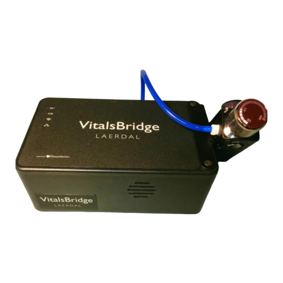
Page 8: Vitalsbridge Overview
VitalsBridge Overview The VitalsBridge consists of a device that allows vital signs from the SimMan 3G or SimMan Essential to be presented on a clinical vital signs monitor. It is intended to increase the fidelity of simulation for users where they may view, interact, and control a vital signs monitor that is used in their clinical practice. -
Page 9: Powering The Vitalsbridge
Powering the VitalsBridge™ External Power To power the VitalsBridge via wall power, simply connect the external power adapter and plug into any standard wall outlet. Caution: Use only the included 24V power supply. Using an incorrect power supply may damage the VitalsBridge and void the warranty. -
Page 10: Network Connections
The VitalsBridge communicates with the SimMan 3G/Essential using via the SimMan 3G’s internal router. The VitalsBridge may be connected to the internal router by an Ethernet cable or by Wifi. In addition to the information below, it is important to follow the procedure for running the VitalsBridge as described on page 24. - Page 11 When connecting the VitalsBridge to the SimMan 3G/Essential manikin using an Ethernet cable, ensure the cable is functional and is securely connected to the Ethernet ports of the VitalsBridge and the manikin. The top of the VitalsBridge indicates when it has established an Ethernet or Wifi connection with the manikin’s internal router.
-
Page 12: Installation Of The Vitalsbridge Software
VitalsBridge Directions for Use (for US Government Customers) Installation of the VitalsBridge Software The VitalsBridge software may be installed on a PC that is able to establish a network connection with the SimMan 3G/Essential manikin or to an instance of the virtual manikin. The instructor application PC is recommended for installation of the VitalsBridge software. - Page 13 VitalsBridge Directions for Use (for US Government Customers) rev. B.10 PN 10229...
- Page 14 VitalsBridge Directions for Use (for US Government Customers) Windows Network Settings Communication between the VitalsBridge instrumentation and the VitalsBridge software occurs over the UDP network protocol on port 14996. The installation software attempts to allow access of this port through the Windows Firewall on both the public and private profiles. For older versions of Windows (e.g., Windows Vista), custom firewall configurations, and custom network settings, consult your IT...
-
Page 15: Cables, Tubing, And Regulator Setup/Configuration
Gently, but firmly, push the manikin skin further down so that it is. Contact Laerdal if additional assistance is needed. - Page 16 VitalsBridge Directions for Use (for US Government Customers) To use the SpO function, ensure the SpO cable is connected to the manikin and the VitalsBridge. connector (to sensor in Manikin's finger) connector (to VitalsBridge) rev. B.10 PN 10229...
-
Page 17: Configuration Of A Compressed Co Source
. The regulator may be detached by lifting the regulator up out of the slot that is on the side of the VitalsBridge. The regulator has a luer lock fitting that will connect into the VitalsBridge, and regulator knob to control the flow of gas. - Page 18 5. Replace the regulator back on the bracket that is attached to the VitalsBridge instrumentation. 6. If the regulator supplied with the VitalsBridge has a maximum pressure of 30 PSI on the gauge, then SLOWLY turn regulator knob clockwise to the “HI” position, usually set at or just above 20 PSI.
- Page 19 This may be accomplished by: (i) turning the regulator to “OFF”, (ii) detaching the female luer fitting from the blue luer lock ring on the VitalsBridge, (iii) slowly turning the regulator knob clockwise (towards “HI”), and (iv) allowing the remaining compressed CO gas to expel in a controlled manner.
-
Page 20: Capnography (Side-Stream End Tidal Co )
Non-invasive Blood Pressure (NIBP) The VitalsBridge is capable of simulating non-invasive blood pressure by simulating the pulsing of the artery. It uses two tubing connections; the red connection provides the pulse, and the green connection measures the pressure in the cuff. The... - Page 21 VitalsBridge Directions for Use (for US Government Customers) The tubing connections to the VitalsBridge are color coded: A 1-tube blood pressure cuff is configured as follows: To VitalsBridge NIBP tubing To NIBP Tubing connection on the patient monitor rev. B.10...
-
Page 22: Invasive Blood Pressure (Ibp)
(PAP) or pulmonary capillary wedge pressure (PCWP). The VitalsBridge simulates the transducer output signal for each invasive blood pressure and utilizes an RJ-11 cable to connect from the VitalsBridge to the patient monitor’s IBP cable. Note: contact Laerdal for assistance with purchasing a VitalsBridge- compatible invasive blood pressure monitoring cable (i.e., the cable that connects from the patient... -
Page 23: Temperature
VitalsBridge Directions for Use (for US Government Customers) When using IBP, all waveforms are not required to for the VitalsBridge to function. Unused IBP ports on the VitalsBridge may be left unconnected. Temperature The VitalsBridge simulates the output of YSI 400 compatible temperature transducers. The temperature cable is a short white cable that consists of a short RJ-11 connector on one end, which connects to the VitalsBridge. -
Page 24: Respiration Impedance Via Electrocardiogram (Ecg)
This connection is utilized with a cable plugged into a connector located on the manikin’s neck. The other end of the cable plugs into the VitalsBridge. Once connected, the patient monitor will display the respiration rate and ECG information. Note: a three lead ECG is recommended with the patient monitor and the SimMan 3G/Essential for respiration impedance simulation. -
Page 25: Running The Vitalsbridge
Step 4: Power on the VitalsBridge instrumentation, wait for network connection. Use the toggle switch, located on the side panel, to power VitalsBridge on or off. Once powered on, the VitalsBridge takes approximately 6-15 seconds to initialize and attempt to connect to the manikin’s internal router. - Page 26 VitalsBridge Directions for Use (for US Government Customers) The VitalsBridge instrumentation has 4 LEDS: Power, battery/charge, WLAN and LAN. Power indicator: o no light: switched off, or switched on and no power to the VitalsBridge o solid: switched on and power available to the VitalsBridge Battery/charge indicator: o no light: VitalsBridge is not running o solid: VitalsBridge is on, battery charge >...
- Page 27 VitalsBridge serial ID and ip address. Upon successful association with the two devices, the main VitalsBridge user interface is shown. A summary of the vital signs that are being sent from the SimMan 3G/Essential to the VitalsBridge is shown.
-
Page 28: Vitalsbridge Software Features
Calibration The VitalsBridge is pre-calibrated with factory settings for a Nellcor standard probe. If the SpO value set on the Instructor Application significantly deviates from the value on the vitals sign monitor, then it is possible to use your own calibration. - Page 29 VitalsBridge Directions for Use (for US Government Customers) Enter the name of the custom calibration. The first portion of the calibration procedure involves scaling the height of the plethysmograph (pleth) waveform. Usually, a scale factor of 4 is best, but may be increased or decreased in size if necessary. If you wish to use a different scaling factor, adjust the scaling factor until a pleth waveform of adequate size is viewed on the vital signs monitor, and there is also a SpO2 reading shown on the monitor.
-
Page 30: Enabling Co 2 Simulation
Enabling CO Simulation Capnography requires use of a pump internal to the VitalsBridge. The pump is active during capnography simulation. Because the pump consumes additional power and adds a moderate level of noise, CO may be disabled. In the VitalsBridge software uncheck the CO option. -
Page 31: Co 2 Calibration
CO waveform on the Instructor Application. From the “Calibrate” tab on the VitalsBridge software, select “(Update)” next to the CO2 label. Select a “(New Calibration)”. Enter the name of the custom calibration. For each calibration point, observe the target etCO value in the CO2 Calibration window. - Page 32 VitalsBridge Directions for Use (for US Government Customers) Note that some vital signs monitors filter and average the end tidal CO value, and there may be a several second delay for the reading to change. Additionally, small CO set values may be difficult to read on the monitor.
-
Page 33: Zeroing The Invasive Blood Pressure(S)
VitalsBridge Directions for Use (for US Government Customers) Zeroing the Invasive Blood Pressure(s) IBPs may be zeroed by setting the blood pressure waveform to “Flat Line” in the Instructor Application for SimMan 3G/Essential. Refer to your patient monitor's documentation for procedures of zeroing the pressures within the monitor's user interface. -
Page 34: Pulmonary Artery Capillary Pressure And Invasive Blood Pressure Offsets
(PCWP) is accomplished by checking the PCWP checkbox. This will send a PCWP waveform from the VitalsBridge to the vital signs monitor using the PAP connection. Note: the Instructor Application does not show the pulmonary capillary wedge pressure waveform; however, one may access and change the PCWP value by clicking on the PAP numeric value in the Instructor Application. -
Page 35: Network Configuration Tool Software
Tool shortcut icon on the PC’s desktop, and a selection window will appear. 10. Wait until the white box is appears with the VitalsBridge that is connected to the manikin. Note: this usually takes a few seconds but may take as long as 30 seconds. - Page 36 VitalsBridge Network Configuration Using an External LAN Consult your network administrator for assistance configuring the VitalsBridge on an external LAN. Using an Ethernet cable, connect the VitalsBridge to a LAN where the PC is located. Note: the local area network must have UDP multicasting installed.
- Page 37 VitalsBridge Directions for Use (for US Government Customers) LAN Manual Connection For a manual LAN, uncheck the “Use DHCP” box in the Network Configuration Tool window, and check the “Assign Manually” box. You may then input the IP, Gateway, and Subnet manually. Note: a manually assigned LAN ip address is not recommended.
-
Page 38: Vitalsbridge Frequently Asked Questions
Q: What is the recommended sequence for starting the VitalsBridge? A: If you have been running the manikin for more than 30 minutes prior to starting the VitalsBridge, it is recommended that you exit the Instructor Application software, and power off the manikin. Power... - Page 39 VitalsBridge Directions for Use (for US Government Customers) Q: Is the VitalsBridge compatible with the Philips flexible finger-cot probe (M1191A) or Philips finger-clip style probe (M1196A)? A: It is possible to use these style SpO sensors, but it is not recommended. Performance is best when using a Nellcor compatible probe.
- Page 40 Temperature Q: My monitor came with a cable that connects from the monitor to a temperature probe; however, it does not fit the short, white, temperature cables that connect to the VitalsBridge. How do I find the right connector? A: You may purchase the proper temperature cable for your Vital Signs Monitor from Laerdal. Consult Laerdal’s website or your local Laerdal sales representative.
Need help?
Do you have a question about the VitalsBridge and is the answer not in the manual?
Questions and answers