Table of Contents
Advertisement
Quick Links
Advertisement
Table of Contents

Related Manuals for laerdal VitalsBridge 100


Summary of Contents for laerdal VitalsBridge 100
-
Page 2: Table Of Contents
VitalsBridge Directions for Use Table of Contents Regulatory Information ........................... 3 Support ..............................3 Warnings and Caution ..........................4 Requirements Checklists .......................... 5 Cables and Accessories ....................... 5 Computer and Software Requirements ..................5 Additional Requirements ......................5 ™ VitalsBridge Overview .......................... - Page 3 Pulmonary Capillary Wedge Pressure Simulation (VB300 only) ........36 Standardized Patients and Low-Fidelity Patient Simulators ............. 36 Laerdal High-Fidelity Patient Simulators .................. 37 Power on the Patient Simulator ..................37 Power on the PC Used to Run the Patient Simulator Software ........37 Power on the VitalsBridge ....................
-
Page 4: Regulatory Information
VitalsBridge Directions for Use Regulatory Information Use statement: The VitalsBridge is for use in the United States, Canada and in CE marking countries. Federal Communications Commission Statement: This device complies with part 15 Subpart B of the FCC rules. Caution: Only use cables supplied with the VitalsBridge and accessories approved for use with the VitalsBridge. -
Page 5: Warnings And Caution
VitalsBridge Directions for Use Warnings and Caution The VitalsBridge is intended solely for use during patient simulation. It is not a medical device. Warning: Never connect the VitalsBridge to a patient. Warning: Never connect the VitalsBridge to a vital signs monitor that is connected to or in use by a patient. Warning: The VitalsBridge is not waterproof. -
Page 6: Requirements Checklists
VitalsBridge Directions for Use Requirements Checklists Cables and Accessories Please verify the following has been included in your shipment. If you are missing any of these items, have damaged items, or need extras, please contact VitalsBridge™ customer support for replacements. VitalsBridge power supply, 9V, with wall plug (all models) Non-Invasive Blood Pressure (NBP) parts kit (array of adapters to connect VitalsBridge to NBP cable on patient monitor;... -
Page 7: Vitalsbridge ™ Overview
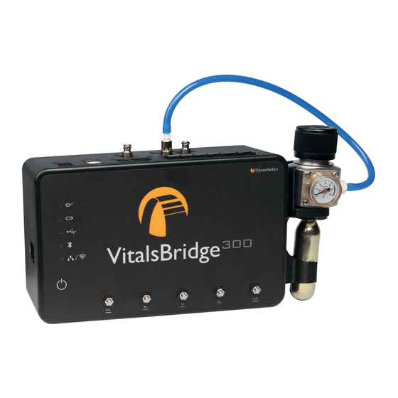
VitalsBridge Directions for Use VitalsBridge Overview ™ The VitalsBridge is a device that allows simulated or digitized vital signs to be presented on a real vital signs monitor. It is intended to increase the realism and effectiveness of simulations by allowing users to view, interact with, and control real patient monitors that are used in their clinical practice. - Page 8 VitalsBridge Directions for Use Each model of the VitalsBridge supports different vital signs and device connection options detailed in the table below: rev. A.5...
-
Page 9: Overview Of The Vitalsbridge Setup
Use the VitalsBridge with a Patient Simulator • Step-by-step instructions start on page Error! Bookmark not defined.. • Communication between the VitalsBridge and Laerdal simulators is available through the VitalsBridge Connector software • The VitalsBridge can be used with a Standardized Patient... -
Page 10: Power On The Vitalsbridge
VitalsBridge Directions for Use Power on the VitalsBridge To power the VitalsBridge via wall power, simply connect the external power adapter and plug into any standard wall outlet. Warning: Use only the included 9V power supply. Prior VitalsBridge models used a different voltage for their power supply. -
Page 11: Internal Battery
VitalsBridge Directions for Use The VitalsBridge instrumentation has 5 LEDS: Power, battery/charge, USB/Serial, Bluetooth and LAN/WiFi. Power indicator: o No light: switched off, or switched on and the VitalsBridge is not plugged into an outlet o Solid: switched on and power available to the VitalsBridge Battery/charge indicator: o No light: VitalsBridge is not running o Solid: VitalsBridge is on, battery charge >... -
Page 12: Connect Patient Monitor Cables And Sensors To The Vitalsbridge
VitalsBridge Directions for Use Connect Patient Monitor Cables and Sensors to the VitalsBridge This section will describe how to connect the cables and tubing between the VitalsBridge and the vital signs patient monitor. The cable and sensor kit provided with the VitalsBridge is intended to be preconfigured with the vital signs monitor brand and model you plan to use. - Page 13 VitalsBridge Directions for Use b. Locate the slot on the Oximeter Adapter box intended for the SpO probe. You should see a white post that simulates a patient finger inside the slot. c. Slide the cable attached to the SpO probe through the slot on the side of the Oximeter Adapter box.
-
Page 14: Mock Spo 2 Probe (Optional)
VitalsBridge Directions for Use Mock SpO Probe (Optional) You will see a port on the Oximeter Adapter box for a mock SpO probe. If the mock probe included in the kit is connected to the Oximeter Adapter box, a reading will not appear on your patient monitor unless the mock probe is placed on a patient simulator’s finger. - Page 15 VitalsBridge Directions for Use i. Determine which connectors your cable will need to connect to the VitalsBridge NBP port. If the NBP tubing coming from your monitor has 2 connectors, a 2-tube to 1-tube adapter fitting has been provided. ii. Follow the instructions with the images below. Select the appropriate tube and luer fittings Affix the tube and luer fittings to each other to provide an ending that can be attached to the monitor NBP tubing...
-
Page 16: Temperature (All Models)
VitalsBridge Directions for Use Temperature (All Models) Video Link: https://youtu.be/jf2nhK77Z1k The VitalsBridge simulates the output of YSI 400-compatible temperature transducers. Configuring ECG 1. Locate the temperature cables. They are short white cables that have an RJ-11 connector on one end and a transducer connector on the other. -
Page 17: Electrocardiogram (Ecg) And Respiration (Vb300, Vb200)
VitalsBridge Directions for Use Electrocardiogram (ECG) and Respiration (VB300, VB200) Video Link: https://youtu.be/TYTOszkZuC8 The VitalsBridge has connections for up to 5 ECG leads (RA, RL, V, LL, and LA). In addition, a respiration by impedance signal is also produced by the VitalsBridge. Configuring ECG 1. -
Page 18: Invasive Blood Pressure (Ibp) (Vb300 Only)
VitalsBridge Directions for Use Invasive Blood Pressure (IBP) (VB300 only) Video Link: https://youtu.be/LcbsGMnd5lQ The VitalsBridge simulates up to 3 different invasive blood pressure waveforms. These include arterial blood pressure (ABP), central venous pressure (CVP), pulmonary artery pressure (PAP) or pulmonary capillary wedge pressure (PCWP). Note: contact Dynasthetics or visit www.vitalsbridge.com for assistance with purchasing a VitalsBridge-compatible... -
Page 19: Install Or Remove The Co Cartridge
VitalsBridge Directions for Use when it is not connected to the VitalsBridge via the luer connection. Only turn the regulator on when a tight secure connection to the VitalsBridge has been verified. Caution: The regulator should be kept horizontal to upright when the CO cylinder is attached. - Page 20 VitalsBridge Directions for Use 3. Attach the blue tubing to the blue luer lock (CO ) to the VitalsBridge. To ensure a secure connection between 2 in the regulator and the VitalsBridge, twist the luer fitting at least 180 degrees to the left before inserting the luer into the metal port on the VitalsBridge.
-
Page 21: Capnography Sampling Line
VitalsBridge Directions for Use Caution: Ensure CO has been fully released prior to disposing of the cartridge. This may be accomplished by: (i) turning the regulator to “OFF”, (ii) detaching the female luer fitting from the blue luer lock ring on the VitalsBridge, (iii) slowly turning the regulator knob clockwise (towards “HI”), and (iv) allowing the remaining compressed gas to expel in a controlled manner. -
Page 22: Install And Run The Vitalsbridge Connector Software
Note: Choose the appropriate VitalsBridge installation software carefully. There may be specific installation software that is compatible with a particular version of a patient simulator (e.g. a particular version of Laerdal’s LLEAP) software. Note: If it is intended for the VitalsBridge to be used in conjunction with Laerdal LLEAP patient simulator software, download the VitalsBridge connector software to the computer where Laerdal’s LLEAP is installed. -
Page 23: Run The Vitalsbridge Connector Software
VitalsBridge Directions for Use Run the VitalsBridge Connector Software If using a PC, double click on the VitalsBridge Connector icon, labeled VitalsBridge Connector, located on the computer's desktop. Alternatively, the software may be located by searching for “VitalsBridge” using the Windows search function (i.e., +S “VitalsBridge”). Connect the VitalsBridge to the Connector Software Once the Connector Application is running, any available VitalsBridge units will appear in the Connection tab (any units connected via Bluetooth, Serial, or Ethernet/Wifi for 200/300 units only). -
Page 24: Vitalsbridge Connector App (Android Mobile Device)
VitalsBridge Directions for Use VitalsBridge Connector App (Android Mobile Device) The VitalsBridge Connector Android App is available for download on the Google Play Store. Using an Android mobile device, navigate to: • https://play.google.com/store/apps/details?id=com.dynasthetics.vitalsbridge Alternatively, open the Google Play Store App on the Android mobile device, and search for ‘VitalsBridge’. -
Page 25: Establish Communication With The Vitalsbridge
VitalsBridge Directions for Use Establish Communication with the VitalsBridge Overview: The communication options between the PC and VitalsBridge are: 1. USB (RS-232) 2. Bluetooth 3. Ethernet 4. WiFi* The communication options between the Android mobile device and VitalsBridge are: 1. Bluetooth 2. - Page 26 VitalsBridge Directions for Use 2. Choose “Add Bluetooth or other device” (ensure that Bluetooth is toggled on). 3. When prompted to add a device, choose Bluetooth. 4. Choose the VitalsBridge. When first connecting, the name of the device will be a unique name followed by a string of 4 characters/numbers (e.g., “Todd-03E0”...
- Page 27 VitalsBridge Directions for Use 5. The VitalsBridge will provide a 6-digit pin, which will need to be confirmed/acknowledged during the pairing process. Select “Connect” when the appropriate screen appears (it is unnecessary to verify this pin number). Brandine-8FEA matches this one.
-
Page 28: Usb Cable
VitalsBridge Directions for Use USB cable Video Link: https://youtu.be/Kk3TU3nHpd0 1. With the supplied USB cable, connect the VitalsBridge to the Windows PC. Standardized Patient Setup Running the VitalsBridge using a Serial Cable With a patient simulator 2. Windows will automatically install the appropriate drivers for RS-232 communication over USB. Please wait approximately two minutes for the appropriate drivers to be installed. -
Page 29: Ethernet/Wifi
VitalsBridge Directions for Use Ethernet/WiFi The VitalsBridge may be connected to a router by an Ethernet cable or by WiFi (2.4 GHz 8.02.11b/g/n). If applicable, the VitalsBridge Connector software is intended to run on a PC that is on the same network as the VitalsBridge and patient simulator (if applicable). - Page 30 VitalsBridge Directions for Use Note: Before completing the process outlined below, you must have already 1) downloaded the VitalsBridge Connector Software, 2) successfully established a connection between your PC and the VitalsBridge via USB or Bluetooth, and 3) connected the VitalsBridge to the connector software. The WiFi SSID and Password may be set for the VitalsBridge in the Configuration tab of the VitalsBridge Connector Software.
-
Page 31: How To Use The Vitalsbridge Connector Software
VitalsBridge Directions for Use How to Use the VitalsBridge Connector Software Before beginning this segment make sure the following have been completed: 1. The VitalsBridge has been connected properly to the patient monitor. 2. The VitalsBridge has been connected properly to the device that will be used to control it. 3. -
Page 32: Calibration And Zeroing
VitalsBridge Directions for Use Note: The ‘Force SpO2 OFF’ option will not result in the plethysmograph waveform to disappear or ‘flat line’ on the patient monitor. Instead, the signal may wander in a manner that allows patient monitors to detect that the SpO probe is off. - Page 33 VitalsBridge Directions for Use Choose a name for the calibration and SUBMIT. The user interface will instruct you to wait for a period of time. This is necessary to allow the SpO reading to stabilize on the vital signs monitor before entering the value, as some vital signs monitors filter and average the SpO value, causing delays.
- Page 34 VitalsBridge Directions for Use Enter the value shown on the patient monitor and SUBMIT. Verify that this reading is from the real vital signs monitor and not a reading from a patient simulator. The process of entering in a SpO value is repeated until enough points are found for an accurate calibration reading.
-
Page 35: Temperature Calibration Selection
VitalsBridge Directions for Use Temperature Calibration Selection The default temperature calibration selection is appropriate for most critical care patient monitors. Select the Default Temperature setting in the Configuration tab of the VitalsBridge Connector. “Spot-Check” Temperature Readings There are a few non-custom calibrations provided for vital signs monitors that have hand-held “Spot Check” temperature probes. -
Page 36: Invasive Blood Pressure Zeroing (Vb300 Only)
VitalsBridge Directions for Use Invasive Blood Pressure Zeroing (VB300 only) IBP may be zeroed by setting the blood pressure waveform to “Flat Line” in the software used to control your patient simulator. Refer to your patient monitor's documentation for procedures of zeroing the pressures within the monitor's user interface. -
Page 37: Other Configuration Settings And Features
Simulator tab to change the waveform from PAP.Use the VitalsBridge with a Patient Simulator The VitalsBridge Connector Software offers direct integration with Laerdal Patient Simulators that are running LLEAP. Other patient simulator brands and models may also be compatible with the VitalsBridge. The VitalsBridge can also be run with low-fidelity manikins and standardized patients. -
Page 38: Laerdal High-Fidelity Patient Simulators
5. Control the desired vitals via the VitalsBridge Connector software. Laerdal High-Fidelity Patient Simulators Before beginning this segment with a Laerdal manikin that is running LLEAP, make sure the following have been completed: 1. The VitalsBridge instrumentation has been set up properly and is connected to any desired monitors. - Page 39 VitalsBridge Directions for Use Ensure the computer can connect to a patient simulator over a network. Then, select the “Simulator” tab in the VitalsBridge Connector software. rev. A.5...
- Page 40 VitalsBridge Directions for Use Select the appropriate patient simulator that is reported in the dialog box and select CONNECT (if Laerdal’s LLEAP software is running, it should automatically appear in the menu). rev. A.5...
-
Page 41: Control Vital Signs For The Vitalsbridge And The Patient Simulator
Use the patient simulator’s application to control whether ECG leads are placed, capnography is enabled, and whether the SpO probe in place by checking the “Learner Patient Monitor Buttons” on the Laerdal control panel for the vital signs you would like to control. -
Page 42: Hints For Increasing Simulation Realism
VitalsBridge Directions for Use Hints for Increasing Simulation Realism Props Various “props” can be used to enhance simulation experience when using the VitalsBridge. None of these props are necessary for the VitalsBridge to run. Only one prop is included with your VitalsBridge. This is the mock SpO probe that is described on page 12. -
Page 43: Frequently Asked Questions
Q: Is the VitalsBridge compatible with Laerdal patient simulators that run on SimPad? A: The VitalsBridge is not SimPad compatible. However, many Laerdal patient simulators that run on SimPad also run on LLEAP, which is compatible with the VitalsBridge. Contact Laerdal for additional details. -
Page 44: Co2
Q: How do I simulate a pulmonary-capillary wedge pressure with the VitalsBridge? A: Ensure the software that controls the patient simulator can send PCWP (e.g., pre-LLEAP Laerdal SimMan 3G’s are incompatible with sending PCWP to the VitalsBridge). Then, follow the instructions on page 36. -
Page 45: Respiration By Ecg Impedance
VitalsBridge Directions for Use Respiration by ECG Impedance Q: I am using a 5-lead ECG on my simulator, but my simulator does not have connections for 5 leads. Will respiration work? A: You may use the 5 ECG posts on the VitalsBridge (200 and 300 models only) to simulate an ECG with respiration impedance.
Need help?
Do you have a question about the VitalsBridge 100 and is the answer not in the manual?
Questions and answers