
Subscribe to Our Youtube Channel
Related Manuals for Briggs & Stratton GC1031


Summary of Contents for Briggs & Stratton GC1031
- Page 1 Operation Instructions GC1031 GENSET Controller Copyright © Briggs & Stratton Corporation 80086364 Milwaukee, WI USA. All Rights Reserved. Revision A Page | i...
- Page 2 Safety Definitions For your safety, the safety of others, and to protect the performance of equipment, obey the warnings in the manual before operation, during operation, and during maintenance procedures. indicates a potential personal injury hazard. DANGER indicates a hazardous situation which, if not avoided, will result in death or serious injury. WARNING indicates a hazardous situation which, if not avoided, could result in death or serious injury.
- Page 3 List of Abbreviations and Acronyms This list contains the abbreviations and acronyms used in this document. Refer to this list for their respective description. Acronym Description Alternating Current Acknowledge Alternator Auto Mains Failure Auxiliary Automatic Voltage Regulator Charging Circuit Current Transformer Direct Current DIG IN Digital Input...
-
Page 4: Table Of Contents
Table of Contents Key Highlights of the Product ..................... 1 Installation ..........................1 Terminal Description ....................... 1 Description of Control Keys ....................4 Functions of Control Keys ..................... 4 Configuration of GCU ......................5 ... - Page 5 List of Figures Figure 1: GC1031 Genset controller from the backside ..............1 Figure 2: Control key function ......................4 Figure 3: Configuration mode screen ..................... 5 Figure 4: Configuration mode authentication page screen ............5 ...
- Page 6 List of Tables Table 1: Voltage input terminology ....................2 Table 2: Details of the GC1031 terminals ..................2 Table 3: Control keys in different modes ..................4 Table 4: Parameters ........................5 Table 5: Alarm actions ........................19 ...
-
Page 7: Key Highlights Of The Product
PC connectivity via USB port, RS485, CAN J1939 protocol Backlit and full graphics display with power saving feature Installation Terminal Description The figure that follows shows the rear view of the controller. Figure 1: GC1031 Genset controller from the backside Page | 1... -
Page 8: Table 1: Voltage Input Terminology
1 Phase 2 wire L1-N 1 Phase 3 wire R-Y-N L1-L2-N 3 Phase 4 wire R-Y-B-N L1-L2-L3-N Table 2: Details of the GC1031 terminals Name Description BATT - Battery negative BATT + Battery positive OUT A High side driver output – A OUT B High side driver output –... - Page 9 Name Description CT – IN B1 CT input 1 from Phase B / L3 CT – IN B2 CT input 2 from Phase B / L3 CT – IN Y1 CT input 1 from Phase Y / L2 CT – IN Y2 CT input 2 from Phase Y / L2 CT –...
-
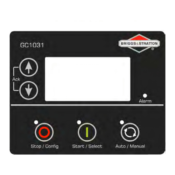
Page 10: Description Of Control Keys
Description of Control Keys Figure 2: Control key function 1. Menu Navigation Up key 2. Menu Navigation Down key 3. Stop/Config key 4. Start/Select key 5. Auto/Manual Mode selection key Functions of Control Keys The table that follows gives a brief overview of different functions of control keys in different modes. Table 3: Control keys in different modes Mode Key input... -
Page 11: Configuration Of Gcu
Before exiting from the configuration mode the controller will show the following screen: Figure 5: Saving settings screen List of Parameters The table that follows gives a brief overview of configurable parameters in GC1031 controller. Table 4: Parameters Level 0 Level 1 (On screen) - Page 12 Level 0 Level 1 (On screen) Level 2 (On screen) Parameters (On screen) Contrast 0 – 100 % (CONTRAST) Display (DISPLAY) Power Save Mode Disable/Enable (POWER SAVE MODE) Communication Mode None/MODBUS (COMM MODE) * Slave ID 1 – 247 (MODBUS SLAVE ID) Communication (COMMUNICATION) * Baudrate...
- Page 13 Level 0 Level 1 (On screen) Level 2 (On screen) Parameters (On screen) (AMB TEMP/DIG G) (USE INPUT AS) In Amb Temp * Circuit Fault Action None/Notification/Warning/ Electrical Trip/Shutdown (CKT FAULT ACTION) * Ambient Temperature Sensor Calibration Table * Use Input As Not used/Digital Input H/Anlg In Fuel LVL (USE INPUT AS)
- Page 14 Level 0 Level 1 (On screen) Level 2 (On screen) Parameters (On screen) ((DIG) ACTIVATION DELAY) * Low Level Shutdown Disable/Enable (SHUTDOWN) * Low Level Shutdown Threshold 0.0 – 9.8 bar (SHUTDOWN THRESHOLD) * Low Level Warning Disable/Enable (WARNING) * Low Level Warning Threshold 0.2 –...
- Page 15 Level 0 Level 1 (On screen) Level 2 (On screen) Parameters (On screen) (GENERAL TIMER) (SAFETY MONITOR DELAY) Mains Detect Delay 1 – 300 sec (MAINS DETECT DELAY) * Alternator Detect Delay 1 – 60 sec (ALT DETECT DELAY) Warm-Up Delay 0 –...
- Page 16 Level 0 Level 1 (On screen) Level 2 (On screen) Parameters (On screen) * Under-voltage Warning Disable/Enable (UNDER VOLT WARNING) * Under-voltage Warning Threshold 55 – 300 Volt Ph-N (UV WARNING THRESHOLD) * Over-voltage Shutdown Disable/Enable (OVER VOLT SHUTDOWN) * Over-voltage Shutdown Threshold 105 –...
- Page 17 Level 0 Level 1 (On screen) Level 2 (On screen) Parameters (On screen) * Over-load Monitoring Delay 1 – 600 sec (OVERLOAD MON DELAY) * Unbalanced Load Action None/Notification/Warning/ Electrical Trip/Shutdown (UNBAL LOAD ACTION) * Unbalanced Load Threshold 5 – 200 % (UNBAL LOAD THRESHOLD) * Unbalanced Load Delay 1 –...
- Page 18 Level 0 Level 1 (On screen) Level 2 (On screen) Parameters (On screen) Sensor (DISCONN ON LOP SENS) * Pressure Sensor Monitoring Threshold 0.5 – 10.0 bar (DISCONN LOP THRESH) * Monitor Pressure Switch Before Crank Disable/Enable (MON LLOP BEFR CRANK) * Monitor Pressure Sensor Before Crank Disable/Enable...
- Page 19 Level 0 Level 1 (On screen) Level 2 (On screen) Parameters (On screen) * High Battery Voltage Threshold 9.0 – 32.0 volt (HIGH VOLT THRESHOLD) * High Battery Voltage Delay 5 – 1800 sec (HIGH VOLT DELAY) Alarm Action Notification/Warning (ACTION) Maintenance Alarm (MAINT ALARM)
-
Page 20: Operating Modes
Level 0 Level 1 (On screen) Level 2 (On screen) Parameters (On screen) (INTEGRAL GAIN) * Derivative Gain (Kd) 0 – 1000 (DERIVATIVE GAIN) * Friction Setoff 0 – 1000 (FRICTION SETOFF) * Gain Schedule Trigger 0.0 – 100.0 % (GAIN SCHEDULE TRIGGER) * Loading Factor 0 –... -
Page 21: Figure 6: Smd For Amf Mode
transferred to the genset. If the Mains voltage returns to normal, the controller will sense this and return the load back to the Mains, further it will stop the genset after a cool down period. Mains = 0 and No Warning/No Electric Trip/No Shutdown Emergency shutdown input = 1 Or Genset shutdown action = 1 Engine Off... -
Page 22: Remote Start/Stop (2 Wire)
4.1.2 Remote Start/Stop (2 Wire) To use the Remote Start/Stop Mode of the controller, the Mains monitoring should be disabled first before using the Remote Start/Stop feature. In this mode, the genset can be commanded to start and stop by activating/deactivating the preconfigured Remote Start/Stop input (active low) in a continuous state. -
Page 23: Manual Mode
Exercise Exercise start time is reached and No Warning / Electrical Trip / Shutdown Present Emergency shutdown input = 1 or Genset shutdown action = 1 Engine OFF Engine Start Engine cooling down in LIM Time >= Auto exerciser mode ON Auto exerciser mode Remaining time <... -
Page 24: Low Idle Mode (Lim)
Start command from key pad = 1 Engine And No Warning / Electrical Trip / Shutdown present = 1 Starts in Engine Off Stop input from Engine Engine * Genset healthy conditions = 1 key = 1 and Time >= Warm up Time or Electric trip enters in cooling... -
Page 25: Alarms
Alarms An alarm condition occurs when a preconfigured parameter is outside of a pre-set level. On initiation of an alarm, the Alarm LED will start blinking and the fault output pin will be activated if configured. The controller will display the name of the alarms along with a count on the ALARMS screen and the nature of alarm on the ENGINE STATUS screen. - Page 26 Alarms Causes Voltage the pre-set over voltage threshold R/L1 Phase Under Indicates that genset L1(R) Phase voltage has fallen Voltage below pre-set under voltage threshold. Y/L2 Phase Under Indicates that genset L2(Y) Phase voltage has fallen Voltage below pre-set under voltage threshold B / L3 Phase Under Indicates that genset L3(B) Phase voltage has fallen Voltage...
-
Page 27: Troubleshooting
Alarms Causes alarm. Clears at the next successful exercise cycle Troubleshooting WARNING Autostart Hazard. With the battery connected the generator may crank and start without warn- ing, resulting in death or serious injury. Before servicing, stop the generator and disconnect the negative (-) cable at the battery. -
Page 28: Table 7: Common Faults And Their Remedial Actions
Table 7: Common faults and their remedial actions Faults Remedial Actions Possible Issues in MANUAL Mode The controller does not power ON. Check the battery voltage. Check the fuse on the battery supply. Check continuity between battery positive and controller terminal # 2. - Page 29 Possible Issues in AUTO Mode The controller does not start the Check the wiring of the “Remote Start” signal to the engine even when a “Remote Start” controller's respective digital input terminal. command is sent from an external Enter “Configuration Mode”...
-
Page 30: Notes
Notes Page | 24... - Page 31 Disclaimer: Due to continuous development, the details provided in this document are subject to change without any prior notice. Page | 25...
Need help?
Do you have a question about the GC1031 and is the answer not in the manual?
Questions and answers
HOW DO YOU MANUALLY TURN IT OFF AND ON WHEN YOU ARE CHANGING BOTTLES OF PROPANE
To manually turn off and on the Briggs & Stratton GC1031 when changing propane bottles, follow these steps:
1. Turn Off (Manual Shutdown):
- Press the “OFF” key on the controller to stop the generator.
- Wait for the generator to completely stop before proceeding.
2. Change the Propane Bottle:
- Ensure all fuel valves are closed.
- Replace the empty propane bottle with a full one, following safety procedures.
- Open the fuel valve after replacement.
3. Turn On (Manual Start):
- Press the “MANUAL” key to enter Manual Mode.
- Press the “START” key to crank and start the generator.
- Observe the generator to confirm it runs normally.
Always follow safety precautions and ensure the generator is stopped before servicing.
This answer is automatically generated
I have a GC 1031 - R8.00 Briggs and Stratton generator. I t has only 54 hours of operation on it and engine status is healthy. I had it running for 12hrs or so and then turned it off overnight. When attempting to start it in the morning I first got an l/p sensor alarm. I cleared the alarm on keyboard and attempted to start it several times. It cranks for a second and immediately stops and won't turn over. Not sure how to remedy this???
The cause of a low-pressure sensor alarm and starting issues with a Briggs & Stratton GC1031 generator could be due to low voltage during auto-exercise, loss of alternator input, or low ambient temperature causing the auto-exercise to be skipped. These conditions can prevent proper startup and trigger alarms.
This answer is automatically generated
auto start skipped
The auto start on the Briggs & Stratton GC1031 may have skipped because the genset was in Auto Exercise Mode. During this mode, the genset will turn on even if the mains power is healthy, but the load will not transfer to the genset, even if "Load transfer is enabled" in the configuration. Additionally, the controller will enter LIM (Load Inhibit Mode) after the first 6 seconds of Auto Exercise Mode, which could affect the auto start process.
This answer is automatically generated
I'm trying to program a controller replacement GC1031 Can you email me the program software , I Have the GC1200 GC1100 sedemac but will not read