
Related Manuals for Campbell AeroX Light


Summary of Contents for Campbell AeroX Light
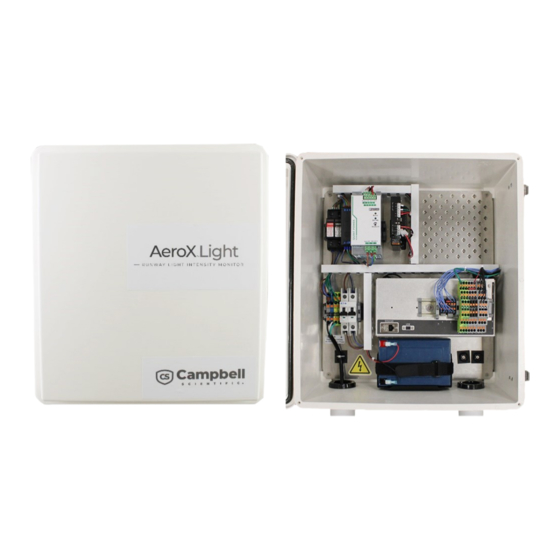
- Page 1 PRODUCT MANUAL AeroX Light Runway Light Intensity Monitor (RLIM) Revision: 04/2023 2023 Copyright © Campbell Scientific, Inc.
-
Page 2: Table Of Contents
Table of contents 1. Introduction 2. Precautions 3. Initial inspection 4. Specifications 4. Schematics 5. Configuration 5.1 Power configuration 5.2 Hardware configuration 5.3 Data logger configuration 5.3.1 Disable unused services 5.3.2 Edit configuration settings 5.4 Current transducer calibration 5.5 Backup and restore 5.6 RLlM to Aero communication flow Table of Contents - i... -
Page 3: Introduction
The LED lights typically use from 0 to 6.6 A and the incandescent lights use 0 to 20 A. The AeroX Light monitors the current and sends the calibrated current data to Campbell Aero for RVR calculations. The Campbell Aero polls the AeroX Light when the data is required. -
Page 4: Precautions
READ AND UNDERSTAND the Safety (p. 19) section at the back of this manual. Although the AeroX Light is rugged, it should be handled as a precision scientific instrument. 3. Initial inspection Upon receipt of the AeroX Light inspect the packaging and contents for damage. File damage claims with the shipping company. -
Page 5: Specifications
AC frequency range: 45 to 65 Hz Inrush surge current: < 15 A (typical) Backup battery: Maintains power to AeroX Light for a minimum of 4 hours Operating temperature: –40 to 85 °C Clamp on current transducer calibration: Software controlled... -
Page 6: Schematics
4. Schematics AeroX Light... - Page 7 AeroX Light...
-
Page 8: Configuration
AWOS/RVR systems deployed may have different requirements such as the quantity of runways, the types of lights, and the reporting requirements. Some Aero systems will need to indicate whether AeroX Light has a backup power system and when the backup power should be used. 5.1 Power configuration No Battery Backup Version: no adjustments. - Page 9 Edge Shield none Black (–) Center Shield none Black (–) Edge Shield none Black (–) Center Shield none Black (–) Edge Shield none Black (–) Center Shield none Black (–) Edge Shield none Black (–) Center Shield none AeroX Light...
- Page 10 [p. 9]). The current transducers are set to the 0 to 10 A scale for the 6.6 A LEDs and to the 0 to 20 A scale for the incandescent lights. This enables the highest resolution of data. Figure 5-2. Current transducer AeroX Light...
-
Page 11: Data Logger Configuration
[p. 10]). The variables are written to the RLIMCalValues constant table in the data logger. Information about changing the variables are provided in Edit configuration settings (p. 12). NOTE: Configuration and calibration data is written to an SD card for later use. AeroX Light... -
Page 12: Disable Unused Services
4. Type CR1000X in the device type window and select the CR1000X Series. 5. Select the Connection Type, Communication Port, and Baud Rate, then click Connect. 6. Click the CS I/O IP tab and uncheck the Enabled boxes. AeroX Light... - Page 13 7. Click the PPP tab and ensure that the Config/Port Used setting is Inactive. 8. Click the GOES tab and ensure that the GOES Enabled box is not checked. 9. Click the Network Services tab and ensure that none of the boxes are checked. 10. Click Apply to save the changes. AeroX Light...
-
Page 14: Edit Configuration Settings
Each runway calibration uses the lowest light level and the brightest light level. The low light level must be entered first, followed by the highest light level. Instructions and feedback are provided in the Calibration_Instructions and Calibration_Message variables. AeroX Light... - Page 15 The program will restart and place the values into the constants table. The Device Configuration utility may need to be reconnected. 8. Turn OFF the runway lights. 9. Repeat the previous steps for each runway lighting loop. The calibration data is contained in the constants table RLIMCalValues. AeroX Light...
-
Page 16: Backup And Restore
Device Configuration utility software to be connected to the data logger USB port. Backup procedure: Create a backup after the AeroX Light RLIM has been fully configured and all current transducers have been successfully calibrated. 1. Connect the data logger USB port to your computer using the supplied USB cable. - Page 17 8. Select the program file (.CR1X) and the calibration file (.cal). 9. Click Next. 10. Click Finish. 11. Select the Settings Editor tab and enter the IP address assigned to the RLIM station. 12. Click Apply. 13. Select the Logger Control tab and click Set Clock. AeroX Light...
-
Page 18: Rllm To Aero Communication Flow
5.6 RLlM to Aero communication flow AeroX Light... - Page 19 See Product Details on the Ordering Information pages at www.campbellsci.com . Other manufacturer's products, that are resold by Campbell Scientific, are warranted only to the limits extended by the original manufacturer. Refer to www.campbellsci.com/terms#warranty for more information.
- Page 20 To obtain a Returned Materials Authorization or Repair Reference number, contact your CAMPBELL SCIENTIFIC regional office. Please write the issued number clearly on the outside of the shipping container and ship as directed. For all returns, the customer must provide a “Statement of Product Cleanliness and Decontamination”...
- Page 21 Do not recharge, disassemble, heat above 100 °C (212 °F), solder directly to the cell, incinerate, or expose contents to water. Dispose of spent batteries properly. WHILE EVERY ATTEMPT IS MADE TO EMBODY THE HIGHEST DEGREE OF SAFETY IN ALL CAMPBELL SCIENTIFIC PRODUCTS, THE CUSTOMER ASSUMES ALL RISK FROM ANY INJURY RESULTING FROM IMPROPER INSTALLATION, USE, OR MAINTENANCE OF TRIPODS, TOWERS, OR...
- Page 22 Campbell Scientific Regional Offices Australia France Thailand Location: Garbutt, QLD Australia Location: Montrouge, France Location: Bangkok, Thailand Phone: 61.7.4401.7700 Phone: 0033.0.1.56.45.15.20 Phone: 66.2.719.3399 Email: info@campbellsci.com.au Email: info@campbellsci.fr Email: info@campbellsci.asia Website: www.campbellsci.com.au Website: www.campbellsci.fr Website: www.campbellsci.asia Brazil Germany Location: São Paulo, SP Brazil...
Need help?
Do you have a question about the AeroX Light and is the answer not in the manual?
Questions and answers