Table of Contents
Advertisement
PW460 Hardware Instruction Manual
PONOVO POWER CO., LTD
No. 139 Jinghai Third Road, BDA, Beijing, China, 100176
Office
TEL. +86 (10) 59089666
E-Mail
Info@relaytest.com
Website
www.relaytest.com / www.ponovo.com.cn
VERSION:
DATE :
This manual is the publisher of PONOVO POWER CO., LTD. To make any kind of copy of this
manual please contact PONOVO POWER CO., LTD in advance.
This manual represents the technical status for the moment of publishing. The product information,
description and specifications mentioned in the manual do not have any contact binding force and
PONOVO POWER CO., LTD remains the right to make modifications to the technical
specifications and configurations without prior notice. PONOVO POWER does not take
responsibility to the possible error/mistakes in this manual.
PW460
HARDWARE INSTRUCTION MANUAL
PW460-AE-2.60
AUGUST 2018
1
Advertisement
Table of Contents

Related Manuals for Ponovo PW460

Summary of Contents for Ponovo PW460
- Page 1 DATE : AUGUST 2018 This manual is the publisher of PONOVO POWER CO., LTD. To make any kind of copy of this manual please contact PONOVO POWER CO., LTD in advance. This manual represents the technical status for the moment of publishing. The product information, description and specifications mentioned in the manual do not have any contact binding force and PONOVO POWER CO., LTD remains the right to make modifications to the technical...
-
Page 2: Table Of Contents
PW460 Hardware Instruction Manual Contents 1. Preface ……………………… Accessories…………………… 27 2. Safety precaution …………. 9.1 PGPS02-GPS-based Synchronization device …….…………………………… 28 3. Designed applications …… 9.2 PIRIG-B Based Synchronization 4. Operation preparation …… device………………………………….. 28 4.1 Preparation …………………. 9.3PSS01 Circuit Breaker Simulator…29 4.2 Connecting PC …………….. -
Page 3: Preface
PW460 Hardware Instruction Manual 1.Preface This manual gives detailed introduction to At the test site user should also refer to other PW460 so that user can have the reasonable, safety and test regulations required by his effective and safe operation of this test kit. -
Page 4: Safety Precaution
PW460 Hardware Instruction Manual 2.Safety Precaution In case the power outlet for powering up the PW460 dose not have protective ground customer must connect the ground socket of PW460 to the protective ground at the test site Please turn off the output before connecting/disconnecting the test object The voltage output of over 36V is considered as dangerous and care must be taken It’s not allowed to feed external voltage into the voltage/current output sockets... - Page 5 PW460 Hardware Instruction Manual For Your Safety Please Note This symbol indicates potential hazards by electrical voltages/currents caused by, for example, wrong connections, short-circuits, technically inadequate or faulty equipment or by disregarding the safety notes of the following sections. Use Proper Power Cord Only the power cord designed for the instrument and authorized by local country could be used.
- Page 6 PW460 Hardware Instruction Manual In order to avoid damages to the device or personal injuries, it is important to operate the device away from an explosive atmosphere. Keep Product Surfaces Clean and Dry To avoid the influence of dust and/or moisture in air, please keep the surface of device clean and dry.
-
Page 7: Designed Applications
PW460 Hardware Instruction Manual 3.Designed Applications Product Features PW460 can be used by power plants, substations, and relay manufactures, etc, for the following test applications. Output sources 6×15A current sources in two groups Test protective relays 4×300V voltage sources... -
Page 8: Operation Preparation
PW460 Hardware Instruction Manual 4.Operation Preparation Preparation Be sure that the following preparation/system components are ready before operating the test equipment: PW460 test equipment Main supply cable (delivered) LAN control cable (delivered) PC with PowerTest software properly installed ... -
Page 9: General Description
PW460 Hardware Instruction Manual 5.General Description Block Diagram PW460 Universal Test System Diagram Power supply and control Power Supply VOLTAGE CONTROL 16 bit D/A Aux DC generator 0-300V DC, 120W Control Signal 6×30A Binary output 1-4 Analog record (optional) (Relay) -
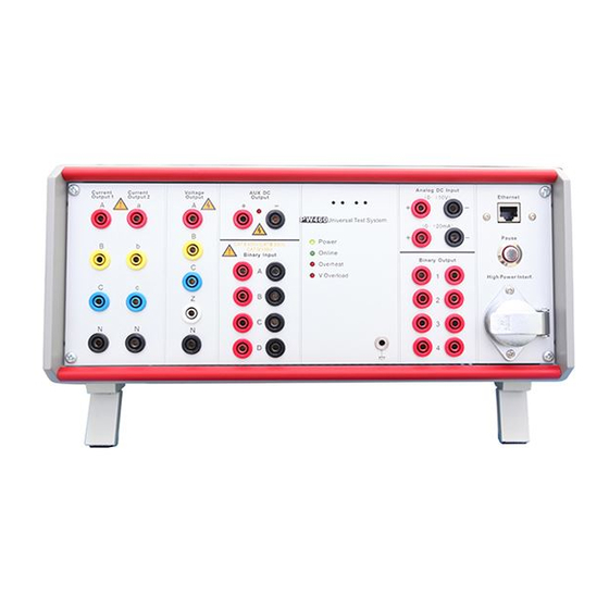
Page 10: Front Panel
PW460 Hardware Instruction Manual Front Panel Current output group 1 Binary input group 1 (A-D) Current output group 2 LED indication Voltage output Earth socket Auxiliary DC 10. Binary output group 1 DC measuring input 11. Pause button RJ45 Ethernet PC control port 12. -
Page 11: Current Booster Interface
PW460 Hardware Instruction Manual Current Booster Interface This interface is used to connect to the external current booster (optional) for testing high burden relays. Signal Current IA Current IN Current IB Current IN Current IC Current IN Current Ia Current In... -
Page 12: Pause Button
PW460 Hardware Instruction Manual Pause Button The Pause button on the front panel is designed to cut the current/voltage outputs either for test purpose or under emergency case. ‘Manual’ control mode ‘Auto’ control mode Push ‘Pause’ button cut the current/voltage... -
Page 13: Rear Panel
PW460 Hardware Instruction Manual Rear Panel Binary input group 1 (E-H) Ethernet 2 Binary output group 2 Connector for mains supply External amplifier / low level output Power switcher interface and binary input group 2 GPS interface IP Reset External Amplifier and Low level Output... - Page 14 PW460 Hardware Instruction Manual Signal Low level output 1 Low level output 2 Low level output 3 Low level output 4 Low level output 5 Low level output 6 Low level output 7 Low level output 8 Low level output 9...
-
Page 15: Gps Interface
PW460 Hardware Instruction Manual GPS Interface This interface is used to connect to our optional PGPS02 GPS-based synchronization device. Signal Contact pin Power Ready DB9 Chassis contact, male ---------------------------------------------- Note: PPS means Pulse Per Second ---------------------------------------------- One popular application of GPS-synchronized control is for end-to-end test for line protection relay... -
Page 16: Ip Reset
PW460 Hardware Instruction Manual IP Reset This reset button is used to restore the IP address of PW460 to the default factory setting. Press this button Switching on the power for PW460 After this operation the IP address will be restored to the following settings. -
Page 17: Hardware Configuration
PW460 Hardware Instruction Manual 6.Hardware Configuration Test modules which requires 6 current mode Current Generators configuration Basic QuickTest (4V,6I) PW460 has 6 current generators in two groups. State sequence (4V, 6I) They can be configured as either 3 currents... - Page 18 PW460 Hardware Instruction Manual 1-phase dc (L-N) 1 × 0 … 20A 1-phase dc (3L-N) 1 × 0 … 60 A Power 3-phase ac (L-N) 3 × 270 VA at 30A 1-phase ac (3L-N) 1 × 540 VA at 90A 1-phase ac (L-L) 1 ×...
-
Page 19: Current In Series Connection In 3 Current Mode
PW460 Hardware Instruction Manual Current in Series Example: Settings in QuickTest (4V, 3I) for IA and IB in series connection Connection in 3 Current Mode In 3 current mode the two current generators can be connected in series to increase the compliance voltage. -
Page 20: Voltage Generators
PW460 Hardware Instruction Manual Voltage Generators PW460 has 4 voltage generators. ---------------------------------------------- Note: The maximum voltage output will become 600Vac in this case ---------------------------------------------- Connect Two Voltage Generators in Series We can connect two voltage generators in series to get higher voltage output range. -
Page 21: Binary Inputs And Outputs
PW460 Hardware Instruction Manual 7.Binary Inputs and Outputs General Description Binary Input PW460 has 8 binary inputs in two groups. The device has 8 binary inputs. Electricity is isolated in A-H. Space contact or active The first group of 4 binary inputs (A, B, C, D) contact (15V-250V) can be set by software. -
Page 22: Polarity Of Binary Inputs
PW460 Hardware Instruction Manual Polarity of Binary Isolation of the Inputs Binary Inputs The polarity reference of the binary inputs is shown below. All 8 binary inputs are gavanically isolated from each other. Binary configuration The software interface for binary configuration (A-H) shows below. -
Page 23: Binary Outputs
PW460 Hardware Instruction Manual At the rear side of the kit there are another 4 Binary Outputs binary outputs 5-8. PW460 has 8 binary outputs in two groups The binary outputs 1-4 are placed on the front panel. These 4 binary outputs are high speed semiconductor type. -
Page 24: Getting Ready For Pc Controlled Operation
2~254 (except 133). Steps for setting IP address for computer. PowerTest test software must be properly installed on the PC to control PW460. The Step 1: Left click ‘Start/Control panel/Network installation description of PowerTest test connection’... - Page 25 PW460 Hardware Instruction Manual Step 2: Right click ‘Local connection’ icon Step 3: Left click the ‘Properties’ ---------------------------------------------- Note: the last section of IP address can be any number between 2-254 (except 133) ---------------------------------------------- Step 5: Make the settings ...
- Page 26 PW460 Hardware Instruction Manual If we see the following display on the right Check if control cable is connected bottom corner then we need to make the Check if PW460 is powered up check as mentioned bellow...
-
Page 27: Pw460-Related Products And
PW460 Hardware Instruction Manual 9.PW460-Related Products and Accessories This chapter describes the optional equipments and accessories for the PW460 test set. Please visit the PONOVO Web site www.ponovo.com.cn for up-to-date information. Optional accessories Standard accessories Item Part No. Item Part No. -
Page 28: Pgps02-Gps-Based Synchronization Device
You can synchronize two or more PONOVO Via the PIRIG-B interface box users can test sets by connecting a PGPS connect devices to the PW460 test set that synchronization unit to each of the test sets’ either transmit or receive the IRIG-B time inputs. -
Page 29: Pss01 Circuit Breaker Simulator
PW460 Hardware Instruction Manual 9.3 PSS01 Circuit Breaker 9.4 Phpc01 Current Booster Simulator Phpc01 current booster is designed to supply high compliance voltage even at small current t can simulate circuit breaker behaviors in range, suitable for testing high burden three pole or 1 pole tripping of 6-500KV electromagnetic current relays. -
Page 30: 9.5 Pacb108 Scanning Head
PW460 Hardware Instruction Manual 9.5 PACB108 Scanning Head Counter Input Cable The passive optical scanning head PACB108 detects the status of an LED, that is either an optical pulse output from an energy meter or the binary status of a protective relay or other similar optical source. -
Page 31: 8.9 Standard Accessories
1. Colour coded current cables SAW0201/ 0203 colour coded current cable Amount: 2xred, 2xblack, 2xyellow, 2xblue xred, 1xblack, 1xyellow, 1xblue The current cables to connect the PW460 output to other safety sockets of, generally the current parts, voltage and signal tripping. - Page 32 SAW0202 Colour coded voltage cable Amount: 1x red, 1x yellow, 1x white, 1x blue, 1x black The voltage cables to connect the PW460 output to other safety sockets of, generally the voltage parts, current and signal tripping. Signal Cable SAW0204/0205 Signal cables...
- Page 33 PW460 Hardware Instruction Manual Flexible Terminal Adapter SAW0206 Flexible terminal adapter Amount: 10xred, 10xblack Flexible terminal adapter connects to screw-clip terminals. -------------------------------------------------------------------------------------- Notes: One end of the adapters have no Users insert the non-safety into the insulator, users should make sure there is terminals and screw it firmly, then connect no output during connecting the adapters.
- Page 34 PW460 Hardware Instruction Manual Jumper Cable SAW0207 Flexible jumpers Amount: 4xblack Flexible jumper connects current outputs in parallel. Crocodile Clips SAW0208 Crocodile clips Amount: 2xred, 2xblack, 2xyellow, 2xblue Crocodile clips for secondary side to connect to pins or screw types.
- Page 35 PW460 Hardware Instruction Manual U Clamps SAW0209 U clamps 1# SAW0210 U clamps 2# Amount: 10xred, 10xblack 5xred, 5xblack It is used to connect test leads with screw type terminals. ------------------------------------------------------------------------------------------ Notes: One end of the adapters have no insulator, users should make sure there is no output during connecting the adapters.
- Page 36 PW460 Hardware Instruction Manual Pin clamps SAW0211 Pin clamps Amount: 4xred, 4xblack It is used to connect test leads with screw type terminals. Banana plug adapter SAW0211 Banana plug adapter Amount: 3xred, 3xyellow, 3xblue, 3xblack Banana plug adapter for screws to connect regular test leads to UK terminals.
- Page 37 D03 Power code QP3D Power code Amount: 1 piece Power cord connects the PW460 with power supply socket. PONOVO will provide relevant plug socket according to different countries. ----------------------------------------------------------------------------------------- NOTE: D03: Adapter is mainly used in German, Finland, France, Norway, Sweden, Poland, South Korean, Austria, Spain, Hungary, Czech, Ukraine, Turkey, Brazil and Russia etc.
- Page 38 Amount: 1 piece Earthing lead connects the PW460 with ground to ensure kit safety. ----------------------------------------------------------------------------------------- Notes: In order to avoid static induction, users should connect the PW460 with ground reliably before testing. ----------------------------------------------------------------------------------------- 12. PC control cable (LAN) SAW0012 PC control cable (LAN) Amount: 1 piece The LAN cable connects the PW460 with PC for communications.
-
Page 39: 9.9.2 Transportation Case
PW460 Hardware Instruction Manual 9.9.2 Transportation Case The large-size case with wheels is designed for heavy transport stress with folding hand it is made of fireproof materials and smooth rolling rubber tires. SAC0105 Transportation case Dimension: 465x250x525mm (WxHxD) Weight: 10kg. -
Page 40: Troubleshooting
PW460 Hardware Instruction Manual 10.Troubleshooting 1. Power Indicator doesn’t work. 1) Check if there is electricity in power supply. 2) Check if the input fuse is blown. If the fuse is broken, check if the input power is correct and change the fuse. There are two fuses in the box which is under the mains jack. One is for working, the other is for reserve. - Page 41 PW460 Hardware Instruction Manual Turn off antivirus software, and then test again. Sometiems computer system may affect online result, please change computers. Please note if the kit IP address has been changed. Press “IP reset” button to switch on kit and confirm the IP in “IP Set”.
- Page 42 PW460 Hardware Instruction Manual Check if the power supply THD exceeds 5%. If it exceeds, the voltage might be inaccuracy or voltage short-circuit alarm while high voltage output. 7. Output waveform is incorrect. Check the setting output value. Check if the open circuit casue no oscillogram.
- Page 43 PW460 Hardware Instruction Manual When the frequency is not accurate, check if the current and voltage’s output frequncy in general unit are correct first. If the frequency differential is beyond the range, please check as following method: 1) Check if the site instrument works well.
- Page 44 PW460 Hardware Instruction Manual 13. How to output a greater current than allowed max. single phase current? The three-phase current power of kit can be used by parallel connection. Users need set the phase output. It is suggested to set amplitude the same.
Need help?
Do you have a question about the PW460 and is the answer not in the manual?
Questions and answers