
Related Manuals for Pulsar PSBSH 2012B


Summary of Contents for Pulsar PSBSH 2012B
- Page 1 PSBSH 2012B v.1.1 PSBSH 13,8V/2A/7Ah/HERMETIC Buffer switch mode power supply unit EN** Edition: 6 from 08.06.2017 Supercedes the edition: 5 from 11.07.2016...
- Page 2 OPTIONAL POWER SUPPLY CONFIGURATIONS: (visualization available at www.pulsar.pl 1. Buffer power supply PSBSH 13,8V/2x1A/7Ah - PSBSH 2012B + LB2 2x1A (AWZ585, AWZ586) + 7Ah 2. Buffer power supply PSBSH 13,8V/4x0,5A/7Ah - PSBSH 2012B + LB4 4x0,5A (AWZ574, AWZ576) + 7Ah 3.
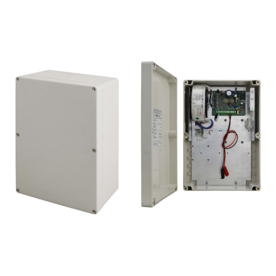
- Page 3 PSBSH2012B (Fig.1) 1.2 Block diagram Fig.1. Block diagram of the PSU. 1.3 Description of PSU components and connectors (Table 1, Fig.2). Table 1. Elements of the PSU pcb (refer to chart 2). Element no. Description ; pins - configuration of UVP battery protection function ...
- Page 4 PSBSH2012B Fig.2. View of the pcb. Table 2. Elements of the PSU ( See fig. 3). Element no. Description Isolation transformer Power-supply unit board ( See tab. 1, fig. 2) TAMPER; microswitches (contacts) for sabotage protection (NC) witch in the power supply circuit 230V, T500mA / 250V...
- Page 5 PSBSH2012B 1.4 Specifications: - electrical parameters (tab.3) - mechanical parameters (tab.4) - operation safety (tab.5) - operating parameters (tab.6) Electrical parameters (tab. 3) PSU type: A (EPS - External Power Source) Mains supply 230V AC (-15%/+10%) Current up to...
- Page 6 PSBSH2012B Operation safety (tab.5). Protection class PN-EN 60950-1:2007 I (first) Degree of Protection PN-EN 60529: 2002 (U) IP65 glands installation required: P9 (Ф 4-8mm) x2 P13,5 (Ф 6-12mm) x1 Electrical strength of insulation: - between input and output circuits of the PSU (I/P-O/P) 3000 V/AC min.
- Page 7 PSBSH2012B 5. Connect the receiver cables to the AUX terminals at the power supply board. 6. If needed, connect the device cables to the technical outputs: - EPS; technical output indicating AC power failure - PSU; technical output indicating PSU failure.
- Page 8 The power supply unit is adapted for a sealed lead-acid battery (SLA). After the operation period it must not be disposed of but recycled according to the applicable law. Pulsar Siedlec 150, 32-744 Łapczyca, Poland Tel. (+48) 14-610-19-40, Fax. (+48) 14-610-19-50 e-mail: biuro@pulsar.pl, sales@pulsar.pl http:// www.pulsar.pl, www.zasilacze.pl...
Need help?
Do you have a question about the PSBSH 2012B and is the answer not in the manual?
Questions and answers