Table of Contents
Advertisement
Quick Links
Advertisement
Table of Contents

Related Manuals for PEERLESS LCT Series


Summary of Contents for PEERLESS LCT Series
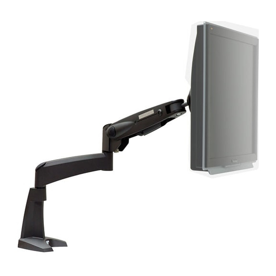
- Page 1 Installation and Assembly: LCT Series LCD Arm Model: LCT 101 Max Load Capacity: 25 lbs (11kg) 3215 W. North Ave. • Melrose Park, IL 60160 • (800) 729-0307 or (708) 865-8870 • Fax: (708) 865-2941 • www.peerlessmounts.com ISSUED: 03-21-05 SHEET #: 090-9103-3 08-03-07...
- Page 2 Note: Read entire instruction sheet before you start installation and assembly. WARNING • Do not begin to install your Peerless product until you have read and understood the instructions and warnings contained in this Installation Sheet. If you have any questions regarding any of the instructions or warnings, please call Peerless customer service at 1-800-729-0307.
- Page 3 Parts List Description Qty. desk base assembly arm assembly plastic cap plastic spacer round head cap screw M8 washer M8 disk spring washer set screw M5 hex wrench M2.5 hex wrench base cushion with double sided adhesive u-bracket M8 threaded rod wing nut M4 hex wrench M4 x 6 mm screw...
- Page 4 Installation to Desk WARNING • Make sure that the supporting surface will safely support the combined load of the equipment and all attached hardware and components. Installation to desk with clamp option Installation with bolt option Attach base cushion (P) to desk base assembly (A) Remove two flat head screws located underneath by the double sided adhesive tape as shown below.
- Page 5 Installing without extension arm (Optional) Remove plastic cap, not shown, exposing round head cap screw. Use M5 hex wrench (I) to remove round head cap screw, M8 washer, and disk spring washer. Place plastic spacer and arm assembly (B) onto the main shaft of the desk base (A) as shown in fig. 4.1. ROUND HEAD CAP M8 WASHER SCREW...
- Page 6 Snap plastic cap (C) into top of arm assembly Place set screw (H) into the back of desk base (B). (A). Tighten with the M2.5 hex wrench (J). Installing monitor Mount the LCD monitor directly to the front plate of arm assembly (B) using the M4 x 10 mm phillips screws (V) or M4 x 6mm phillips screws (U).
- Page 7 If extension arm is installed, route monitor cables Cable management through two 4" x 2.5 mm cable ties, as shown. Route monitor cables through the cable mount at the Note: To allow free motion of monitor and arm and bottom of arm assembly (B). extension, leave sufficient slack in the cables.
Need help?
Do you have a question about the LCT Series and is the answer not in the manual?
Questions and answers