Advertisement
Quick Links
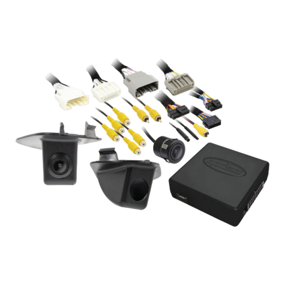
KIT COMPONENTS
• A) Camera and wiring (2) • B) Camera pods (2) • C) AX-ADDCAM and harnessing
A
iBEAM Vehicle Safety Systems
®
Ford F-150 Side View Camera Kit
Visit
iBeamUSA.com
applications
B
C
iBEAMUSA.com
2015-2017
for more detailed information about the product and up-to-date vehicle specific
© COPYRIGHT 2019 METRA ELECTRONICS CORPORATION
TE-FORD-SV-1
I N S TA L L AT I O N I N S T R U C T I O N S
TABLE OF CONTENTS
Camera Installation ........................................... 2-5
App Configuration .................................................6
Camera Specifications ...........................................7
TOOLS REQUIRED
• 7mm screwdriver • Cutting tool
• File or roto tool • Tape • Pry tool
Attention!
Let the vehicle sit with the key
out of the ignition for a few minutes before
removing the factory radio. When testing the
aftermarket equipment, ensure that all factory
equipment is connected before cycling the
key to ignition.
REV. 2/26/19 INSTTE-FORD-SV-1
Advertisement

Related Manuals for iBeam TE-FORD-SV-1


Summary of Contents for iBeam TE-FORD-SV-1
- Page 1 When testing the aftermarket equipment, ensure that all factory equipment is connected before cycling the key to ignition. iBEAM Vehicle Safety Systems iBEAMUSA.com ® © COPYRIGHT 2019 METRA ELECTRONICS CORPORATION REV. 2/26/19 INSTTE-FORD-SV-1...
- Page 2 CAMERA INSTALLATION Radio removal: 1. Remove the panel highlighted from the pocket area (Figure A) 2. Remove (2) 7mm screws exposed within the cavities forward of the center channel speaker. (Figure B) 3. Pop up the pocket panel and remove (2) 7mm screws from the top of the front facing radio panel.
- Page 3 CAMERA INSTALLATION (CONT.) Door panel removal: 6. There are (7) 7mm screws to remove the door panel. (Figure E) 7. It is suggested for the speaker be removed to provide easier access to run the wiring into the vehicle. There are (4) 7mm screws to remove the speaker.
- Page 4 CAMERA INSTALLATION (CONT.) 10. After the wire from the camera is ran into the interior of the door panel, follow the route that is shown in the picture below. Cut a small hole or slit in the cover that is also shown in the picture below, indicated by a circle.
- Page 5 CAMERA INSTALLATION (CONT.) 13. After the boot is back in place and the 18. Once the wires are at the radio location, connect the connectors are plugged back into the appropriate T-harnesses provided with the kit. 4.2” connector, run the camera cable to screen models will use the 12-pin T-harness;...
- Page 6 APP CONFIGURATION 1. Download and install the Axxess Updater from www. axxessinterfaces.com. Open the app, then select Add-Cam Configuration. (Figure A) 2. Select the year and screen size of the vehicle from the drop down menus, then click the Configuration tab at the top.
- Page 7 CAMERA SPECIFICATIONS Sensor CMOS 7080 Resolution 480 TV Lines Field of view Diagonal 170º, Horizontal 110º, Vertical 90º Illumination 0.6 Lux IP rating IP67 Parking Lines None Extension cable 26’ TV system NTSC Working Temp -20ºC ~ 70ºC Warranty 3 years REV.
- Page 8 Log onto www.installerinstitute.com or call 800-354-6782 for more information and take steps toward a better tomorrow. Metra recommends MECP certified technicians iBEAM Vehicle Safety Systems iBEAMUSA.com ® © COPYRIGHT 2019 METRA ELECTRONICS CORPORATION REV. 2/26/19 INSTTE-FORD-SV-1...
Need help?
Do you have a question about the TE-FORD-SV-1 and is the answer not in the manual?
Questions and answers