Table of Contents
Advertisement
Quick Links
La Marche Manufacturing Company | www.lamarchemfg.com
RHF
RHF
RHF
RHF
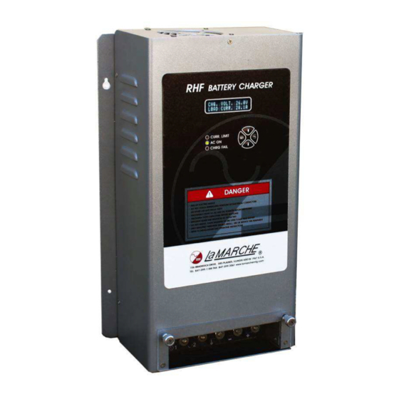
Railroad High Frequency Battery Charger
106 Bradrock Dr. Des Plaines 60018-1967
Tel: 847 299 1188
Fax: 847 299 3061
Installation and Operation Manual
Instruction Drawing Number: P25-LRHF-1
Revision A05
Rev. Date: 8/15
i
ECN: 20928
Advertisement
Table of Contents

Subscribe to Our Youtube Channel
Related Manuals for La Marche RHF


Summary of Contents for La Marche RHF
- Page 1 La Marche Manufacturing Company | www.lamarchemfg.com Railroad High Frequency Battery Charger Installation and Operation Manual 106 Bradrock Dr. Des Plaines 60018-1967 Instruction Drawing Number: P25-LRHF-1 Tel: 847 299 1188 Fax: 847 299 3061 Revision A05 Rev. Date: 8/15 ECN: 20928...
- Page 2 Important Safety Instructions Before using this equipment read all manuals and other documents related to this unit and other equipment connected to this unit. Always have a copy of a units manual on file nearby, in a safe place; if a replacement copy of a manual is needed it can be found at the www.lamarchemfg.com.
- Page 3 In the unlikely event of internal damage, please inform the carrier and contact La Marche for advice on the risk due to any damage before installing the product. Verify that you have all the necessary parts per your order for proper assembly.
-
Page 4: Table Of Contents
Table of Contents Important Safety Instructions ........................ii Table of Contents ............................. iv RHF General Description ......................... 5 Standard Features ..........................5 Installation ............................6 Mounting ............................ 6 Connections ..........................6 1.2.1 Charger Fail Alarm (located on the bottom of the unit) ............. 6 1.2.2... -
Page 5: Rhf General Description
Remote shutdown allows you to place the charger offline for battery testing purposes. The RHF series is equipped with AAR style hardware on the input and output connections. Temperature compensation is standard to increase the longevity of the batteries and charger. -
Page 6: Installation
1.2.1 Charger Fail Alarm (located on the bottom of the unit) The RHF unit is equipped with a single set of Form C dry type relay contacts for Charger Fail Alarm. The Alarm will activate when the unit is unable to regulate the output voltage. -
Page 7: External Temperature Compensation (Optional)
Charger Fail Alarm Contacts DC Output Fuses Bottom of the RHF unit 1.2.3 DC Output Fuses For protection purposes the RHF unit is equipped with two DC output fuses located on the bottom of the unit. Refer to the image above. -
Page 8: Operation
Once all connections have been made and the input cable is plugged into the AC source, the unit will automatically power up. At the initial startup the RHF will run at the default settings (26 Volt Output for 24V units and 13 Volt Output for 12V units. Current Limit is set to 105%). In order to change these settings simply press the SET button to enter configuration mode. -
Page 9: Setting Output Voltage
Press the SET switch with “MAINS VOLTAGE” selected in order to view the Voltage from the AC mains. The Mains Voltage is not a setting; it is simply a way to view the AC Voltage present to the RHF. Press BACK to return to the configuration menu. -
Page 10: Temperature Compensation
Press the SET switch with “TEMP. COMP.” selected in order to set Temperature Compensation. The asterisk (*) on the display indicates the current setting. When enabled the output voltage will change dynamically in respects to the internal temperature of the RHF. > TEMP. COMP. -
Page 11: Default Setting
Go to the Internet Protocol (TCP/IP) Properties in windows and change the computer IP address using the specified Subnet mask (255.255.255.0). The RHF is setup with a Static IP. The default static IP is 192.168.1.100. If more than one RHF are to be used on a network, the IP address will need to be changed manually. - Page 12 To change the IP address, enter 192.168.1.100 into the browser address bar. The RHF home page shown on the next page will load. Click the network configuration button to the left. The IP address can be changed on the network configurations page Open an internet browser and type the default IP address in the address bar.
- Page 13 The Board Configuration screen includes the MAC Address, the name of the RHF, and all of the IP information. The name can be changed to differentiate the different RHF units connected on the same network. In the example below, we change the “Host Name” to LMC1 and the “IP Address” to 192.168.1.26 .
- Page 14 Page below allows the configuration of the SNMP settings. As soon as the Save Config button is clicked, the website will show the following message. The connection to the RHF will be lost.
-
Page 15: Ethernet Led Indicators
(LMC1 in this example). If everything has been done correctly the RHF is now setup to be operated on the Local Network. Follow this same procedure to setup addition RHF systems. Make sure that the IP address and name for each RHF is different. -
Page 16: Document Control And Revision History
Document Control and Revision History Part Number: 126086 Instruction Number: P25-LRHF-1 Issue ECN: 19882 – 2/13 20508-7/14 20536 - 8/14 20551-8/14 20559-9/14 20928-8/15...
Need help?
Do you have a question about the RHF and is the answer not in the manual?
Questions and answers