Table of Contents
Advertisement
Quick Links
INSTRUCTION MANUAL
Keep this manual in a safe place for future reference
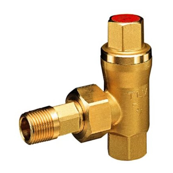
Radiator Trap
Thank you for purchasing the
Radiator Trap.
This product has been thoroughly inspected before
being shipped from the factory. When the product is
delivered, before doing anything else, check the
specifications and external appearance to make sure
nothing is out of the ordinary. Before beginning
installation or maintenance, please read this manual to
ensure correct usage of the product.
This instruction manual is needed not only for
installation, but for subsequent troubleshooting.
Please keep it in a safe place for future reference.
The contents of this manual are subject to change without notice.
1. Safety Considerations
Use only under conditions in which no water hammer will occur. The impact
of water hammer may damage the product, leading to fluid discharge, which
may cause burns or other injury.
Install properly and DO NOT use this product outside the recommended
operating pressure, temperature and other specification ranges. Improper
use may result in such hazards as damage to the product or malfunctions
which may lead to serious accidents. Local regulations may restrict the use
of this product to below the conditions quoted.
Use only under conditions in which no freeze-up will occur. Freezing may
damage the product, leading to fluid discharge, which may cause burns or
other injury.
Take measures to prevent people from coming into direct contact with
product outlets. Failure to do so may result in burns or other injury from
the discharge of fluids.
CAUTION
Do not use excessive force when connecting threaded pipes to the
product. Over-tightening may cause breakage leading to fluid discharge,
which may cause burns or other injury.
Be sure to use only the recommended components when repairing the
product, and NEVER attempt to modify the product in any way. Failure to
observe these precautions may result in damage to the product or burns
or other injury due to malfunction or the discharge of fluids.
When disassembling or removing the product, wait until the internal
pressure equals atmospheric pressure and the surface of the product has
cooled to room temperature. Disassembling or removing the product
when it is hot or under pressure may lead to discharge of fluids, causing
burns, other injuries or damage.
Installation, inspection, maintenance, repairs, disassembly, adjustment
and valve opening/closing should be carried out only by trained
maintenance personnel.
2. Specifications
Model
Maximum Operating Pressure
Maximum Operating Temperature
Maximum Allowable Pressure
Maximum Allowable Temperature
Set Condensate Discharge Temperature
* Maximum allowable pressure (PMA) and maximum allowable temperature (TMA) are
PRESSURE SHELL DESIGN CONDITIONS (NOT OPERATING CONDITIONS)
3. Configuration
H
1
L
4. Proper Installation
1. Before installation, be sure to remove all protective seals.
2. Before installing the product, open the inlet valve and blow out the piping to remove any
piping scraps, dirt and oil. Close the inlet valve after blowdown.
3. Install the product so the arrow on the body is pointing in the direction of condensate flow.
4. Install in the piping with the inlet horizontal and the outlet vertical.
5. Install a condensate outlet valve and piping.
6. Open the inlet and outlet valves gradually and check to make sure that the product
functions properly.
If there is a problem, determine the cause using the "Troubleshooting" section in this manual.
RT3A
RT3A
PMO
0.3 MPaG / 3.0 barg / 45 psig
TMO
144 °C / 292 °F
PMA*
0.3 MPaG / 3.0 barg / 45 psig
TMA*
144 °C / 292 °F
approx. 95 – 100 °C / 203 – 212 °F
No.
Name
No.
1
Body
10
Snap Ring
2
Cover
11
Valve Seat Gasket
3
Thermo-element
4
Valve Seat
12
Cover Gasket
5
Element Guide
13
Union Nipple
6
Valve
14
Union Nut
7
Spring Holder
15
Union Gasket
8
Return Spring
16
Nameplate
9
Over expansion Spring
Diameter
L
mm
(in)
mm
(in)
15 (
/
)
80 (3
/
)
1
1
2
8
20 (
/
)
87 (3
/
)
3
3
4
8
5. Inspection and Maintenance
Operational Check: A visual inspection of the following items should be done on a daily
basis to determine whether the product is operating properly or has failed. Periodically (at
least biannually) the operation should also be checked by using diagnostic equipment such
as a stethoscope.
If the trap should fail, it may cause damage to piping and equipment, resulting in faulty or low
quality products or losses due to leakage.
Normal:
Blocked:
(No Discharge)
Blowing:
Steam Leakage: Live steam is discharged through the trap outlet together with condensate,
(When conducting a visual inspection, flash steam is sometimes mistaken for steam
leakage. For this reason, the use of a steam trap diagnostic instrument [such as TLV
Pocket TrapMan if appropriate] in conjunction with the visual inspection is highly
recommended.)
Parts Inspection: When parts
have been removed, or during
periodic inspections, use the
following table to inspect the
parts and replace any that are
found to be defective.
6. Disassembly / Reassembly
Use the following procedures to remove components. Use the same procedures in
reverse to reassemble.
Part
Union Nut
If removing the trap from the
piping, first remove the union
nut with a wrench (see size
right)
Union Nipple
Remove from piping only if
necessary (see size right)
Union Gasket
Cover
Remove the cover from the
body using a 24 mm (
wrench (do not disassemble
the cover itself)
Cover Gasket
Thermo-
Remove from the body being
element
careful not to bend the push-
pin
Element Guide
Remove from the body being
(Valve)
careful not to scratch the
valve seating surface
Return Spring
Remove from the body
Valve Seat
Remove from the body using
a 12 mm (
being careful not to scratch
seat surface
Valve Seat
Gasket
7. Troubleshooting
When the product fails to operate properly, use the following table to locate the cause.
Problem
Name
No condensate
There is a build-up of sticky scale between the element
is discharged
guide and the body
or discharge is
The thermo-element is misshapen
poor
The trap operating pressure exceeds the maximum
specified pressure or there is insufficient pressure
differential between the trap inlet and outlet
The capacity of the trap is insufficient
Steam locking has occurred
Steam is
The thermo-element is leaking wax
discharged or
leaks from the
There is a build-up of sticky scale between the element
outlet
guide and the body
(blowing)
H
1
The valve and/or valve seat is worn
(steam
mm
(in)
leakage)
35 (1
/
)
3
The valve is catching due to sticky build-up
8
41 (1
/
)
5
8
The valve seat gasket is damaged
Steam or
The cover gasket is damaged
condensate is
Improper cover tightening torque was used
leaking from a
Stress from the piping is exerted on
place other
the union
than the outlet
Manufacturer:
881 Nagasuna, Noguchi, Kakogawa, Hyogo 675-8511, Japan
Tel: [81]-(0)79-422-1122
Copyright
2014 by TLV Co., Ltd. All rights reserved
c
Condensate is discharged together with a small amount of flash steam. The
trap usually operates intermittently or with continuous dripping.
No condensate is discharged. The surface temperature of the trap is low.
Live steam continually flows from the outlet and there is a continuous
hissing sound of flow.
accompanied by a high-pitched sound.
Gaskets
Check for warping and damage
Valve
Check for scratches, warping and wear
Coil Springs
Check for abnormalities
Thermo-element
Check for signs of wax leakage
Valve Seat
Check for scratches, warping and wear
During Disassembly
During Reassembly
—
—
Replace with new if warped
—
or damaged
Tighten to a torque of
.
.
/
")
40 N
m (29 lbf
ft)
15
16
Replace with new if warped
—
or damaged
Replace with a new thermo-
element if damaged or
leaking wax
Insert into body being careful
not to scratch the valve
surface
Place inside body
Insert being careful not to
/
") box wrench,
scratch seat surface; tighten
15
16
to a torque of
.
.
15 N
m (11 lbf
ft)
Replace with new if warped
—
or damaged
Cause
Fax: [81]-(0)79-422-0112
Procedure
Exploded View:
Cover
(Contains the over-
expansion spring,
spring guide, snap ring)
Cover Gasket
Thermo-element
Element Guide
(Valve)
Return Spring
Valve Seat
Valve Seat
Gasket
Union Gasket
Union
Nipple
Body
Union Nut
Distance Across Flats
mm (in)
RT3A
Union
Union
Size
Nut
Nipple
/
/
/
15 (
)
32 (1
)
19 (
)
1
1
3
2
4
4
20 (
/
)
38 (1
/
)
24 (
/
)
3
1
15
4
2
16
.
.
m ~ ~ 10 kg
1 N
cm
Remedy
Clean the element guide and the
inside of the body
Replace with a new thermo-element
Compare specifications and
actual operating conditions
Compare specifications and
actual operating conditions
Study and correct the piping
Replace with a new thermo-
element
Clean the element guide and the
inside of the body
Replace with a new valve and/or
valve seat
Clean the valve and valve seat
surfaces
Replace with a new gasket
Replace with a new gasket
Tighten to the proper torque
Correct the piping
Printed on recycled paper
Rev. 12/2014 (M)
Advertisement
Table of Contents

Related Manuals for TLV RT3A


Summary of Contents for TLV RT3A
- Page 1 The contents of this manual are subject to change without notice. (When conducting a visual inspection, flash steam is sometimes mistaken for steam leakage. For this reason, the use of a steam trap diagnostic instrument [such as TLV Pocket TrapMan if appropriate] in conjunction with the visual inspection is highly recommended.)
- Page 2 North Carolina corporation (“TLV”) warrants that products which OR REPLACEMENT OF THE CLAIMED DEFECTIVE PRODUCT are sold by it or TLV International, Inc., a Japanese corporation ARE SOLELY THE RESPONSIBILITY OF BUYER OR THE (“TII”), which products (the “Products”) are designed and FIRST END USER.
Need help?
Do you have a question about the RT3A and is the answer not in the manual?
Questions and answers