Table of Contents
Advertisement
Quick Links
Advertisement
Table of Contents

Related Manuals for TLV PN-COSR-16


Summary of Contents for TLV PN-COSR-16
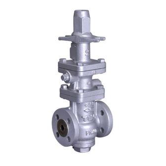
- Page 1 172-65604MA-00 (PN-COSR-16 Pneumatic Control Valve) 10 September 2014 ISO 9001/ ISO 14001 Manufacturer Kakogawa, Japan is approved by LRQA LTD. to ISO 9001/14001 Pneumatic Control Valve for Steam PN-COSR-16 Copyright © 2014 by TLV CO., LTD. All rights reserved...
-
Page 2: Table Of Contents
The PN-COSR-16 can operate automatically and provide accurate pressure control and temperature control when combined with the SC-F70 digital indicator controller or a general-purpose controller. -
Page 3: Safety Considerations
The three types of cautionary items above are very important for safety: be sure to observe all of them as they relate to installation, use, maintenance and repair. Furthermore, TLV accepts no responsibility for any accidents or damage occurring as a result of failure to observe these precautions. - Page 4 Be sure to use only the recommended components when CAUTION repairing the product, and NEVER attempt to modify the product in any way. Failure to observe these precautions may result in damage to the product and burns or other injury due to malfunction or the discharge of fluids.
-
Page 5: Specifications
5% of rated flow rate (1 MPa = 10.197 kg/cm For process temperature control, the desired process temperature must be controllable by a secondary pressure within the adjustable pressure range of the PN-COSR-16. 172-65604MA-00 (PN-COSR Pneumatic Control Valve) 10 Sep 2014... -
Page 6: Correct Usage Of The Pn-Cosr-16
If an on-off valve, such as a motorized valve, is required to stop supply of steam to the steam-using equipment, install it at the inlet side of the PN-COSR-16. If a solenoid valve is installed at the outlet of the PN-COSR-16, its opening and closing will cause heavy chattering and may lead to damage of the piston and main valve. - Page 7 In order to ensure stable steam flow, the piping upstream and downstream of the PN- COSR-16 must be straight runs. If the PN-COSR-16 is installed either directly before or after an elbow or control valve, unevenness in steam flow may result in chattering and unstable pressure.
-
Page 8: Configuration
Configuration 15 – 25 mm ( – 1 in) Name Main Body Cover Plug Cover Plug Gasket Main Valve Seat Main Valve Seat Gasket Main Valve Main Valve Holder Main Valve Spring Sleeve 10 Cylinder 11 Piston 12 Piston Ring 8 mm ( 13 Tension Ring Motive Air Port... - Page 9 40, 50 mm (1 , 2 in) Name 1 Main Body 2 Cover 3 Cover Gasket 4 Main Valve Seat 5 Main Valve Seat Gasket 6 Main Valve 7 Main Valve Holder 8 Main Valve Spring 9 Sleeve 10 Cylinder 11 Piston 12 Piston Ring 8 mm (...
-
Page 10: Installation
Locations with heavy vibration or shock Locations with high inductive interference or other factors that would have a harmful effect on electrical circuitry* *When the PN-COSR-16 is used with electrical equipment such as an electro- pneumatic transducer, controller, etc. 1. Blowdown... - Page 11 The spacer should consist of a spacer, gaskets, bolts and nuts. Fit gaskets to both sides of the spacer Incorrect between the PN-COSR-16 outlet spacer location and the pipe flange. Fasten with bolts and nuts. 5. Piping Support...
- Page 12 30 m/s (100 ft/s). If the distance between the PN-COSR-16 and the steam-using equipment is great, a possible drop in pressure should be taken into consideration when selecting the piping size.
- Page 13 Keep the shutoff valve open at all times during operation. If the shutoff CAUTION valve is closed,PN-COSR-16 will fully open and PRIMARY PRESSURE WILL BE SUPPLIED TO THE EQUIPMENT (see “Piping Example” on next page). Non-North American Models:...
- Page 14 All models except North American models are factory prepared for internal sensing. When internal pressure sensing is required for North American models, please contact the nearest TLV representative to request both a connecting tube, which must be installed in place of the blind pin, and a threaded secondary pressure sensing plug.* Follow the connecting tube installation procedure shown below:...
-
Page 15: Operation
The wiring, etc. should be carried out according to the instruction manual for the controller, the electro-pneumatic transducer, or related devices. Please set the position of the adjustment screw on the PN-COSR-16 according to the steps shown in the “Setting the pressure with the adjustment screw”. - Page 16 (with relief) When operating the PN-COSR-16 remotely by manual operation, an air regulator (with relief function) that adjusts motive air pressure is required. Adjust the set pressure with the air regulator while checking the pressure gauge on the secondary side.
- Page 17 7. Slowly, fully open the shut-off valve at the secondary side of the PN-COSR-16. After setup, put the spanner cap back on. 8. When shutting down the system, always close the shut-off valve at the outlet first and then the inlet.
-
Page 18: Maintenance
If such work is carried out with the power on, there is a danger that equipment may malfunction or electric shock may occur, leading to injury or other accidents. Operational Check To ensure long service life of the PN-COSR-16, the following inspection and maintenance should be performed regularly. Part Inspection and Maintenance Frequency Pilot Screen Disassemble and clean annually. -
Page 19: Disassembly
Wait for the body to cool before attempting to remove the PN-COSR-16 from the line as it may be heated with the residual heat of steam. Then remove the inlet and outlet flange retaining bolts and nuts to permit removal of the PN-COSR-16. - Page 20 Disassembling the Pilot Section The diaphragm is removed by utilizing the notch in the pilot body. Loosen the pilot valve seat with a box wrench and remove it. Lift the pilot valve spring up and out with a pair of tweezers.
- Page 21 Disassembling the Main Valve / Cover Section Turn the PN-COSR-16 upside down for easy dismantling of the main valve. Loosen the cover plug (15 – 25 mm (( – 1 in)) or cover bolts (40, 50 mm (1 , 2 in)).
- Page 22 Exploded View 40, 50 mm (1 , 2 in) Adjustment Section (Drive Section) Pilot Section 15 – 25 mm ( – 1 in) Piston / Main Valve Section NOTE: Configuration of each part varies depending on nominal size. 172-65604MA-00 (PN-COSR Pneumatic Control Valve) 10 Sep 2014...
-
Page 23: Reassembly
1) Fit the piston ring to the outside of the tension ring. 2) The ring gaps should be opposite each other. 5. Standard fastening torque and the distance across flats for the tools to be used are as follows: PN-COSR-16 Distance Tightening Torque Connection Size Across Flats Part... -
Page 24: Troubleshooting
This product is shipped after stringent checks and inspection and should perform its intended function for a long period of time without failure. However, should there be any problem encountered in the operation of the PN-COSR-16, consult the troubleshooting guide below. - Page 25 The diaphragm is Replace with a new distorted or damaged diaphragm There is fluctuation in Check the flow rate; replace the PN-COSR-16 steam consumption if necessary The PN-COSR-16 is Check the model selection, replace the PN- inappropriate for the...
-
Page 26: Product Warranty
One year following product delivery. 2. Warranty Coverage TLV CO., LTD. warrants this product to the original purchaser to be free from defective materials and workmanship. Under this warranty, the product will be repaired or replaced at our option, without charge for parts or labor.
Need help?
Do you have a question about the PN-COSR-16 and is the answer not in the manual?
Questions and answers