
Related Manuals for Tuthill HD Series


Summary of Contents for Tuthill HD Series
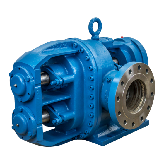
- Page 1 Installation and Service Instructions HD Series Pumps Excellence at work. Excellence in life.
-
Page 2: Table Of Contents
Installation Major Disassembly Instructions Packing Adjustment Reassembly Lubrication Requirements Chamber Clearances Lubrication Instructions for Tuthill Process Pumps Packings 70A, 120A, and 330 Pumps Isometric Drawing Torque For Shaft Locknuts (Models Starting w/ O5 & Packing) Torque For Faceplate Bolts General Parts List for 70A, 120A, and 330 Pumps... -
Page 3: Introduction
Introduction The HD Series pumps have been certified to the requirements of the ATEX Directive 94/9/EC for use in Category II, Group 2 G applications. Read this manual before operating or working on the HD Series pumps. If additional information is required to facilitate operation or maintenance, contact the authorized Tuthill distributor shown at the back of this service manual. -
Page 4: Hd Models
HD Models Material of Size Max. Capacity Max. Pressure Weight Port Size Construction Speed (Internal NPT) USGPM LPM 24.7 10.3 1-1/2” Top 1-1/2” Front 67.5 10.3 2” Top 2” Front 10.3 3” Top 3” Front 67.5 27.5 3” Top 2” Front 120A 27.5 4”... -
Page 5: Hd Process Pump Numbering System
HD Process Pump Numbering System DIGITS 1 & 2 O1-INDUSTRIAL DUTY O5 – INDUSTRIAL DUTY O2-STANDARD DUTY O4-STANDARD DUTY (ID) (ID) Only Models with (SD) Ductile Iron Only (SD) Stainless Steel Only DIGITS 3 & 4 05 – Model 30 01 –... -
Page 6: Temperature Limits Of Hd Process Pump Materials
Temperature Limits of HD Process Pump Materials 600 °F 550 °F 525 °F 500 °F 450 °F 400 °F 350 °F 300 °F 250 °F 200 °F 150 °F 100 °F 50 °F 0 °F -40 °F Note: Viton and PTFE oil seals can be used in place of standard oil seals upon request. PTFE and Gore-Tex gaskets can be used in place of standard seals upon request. -
Page 7: Installation
WARNING Failure to follow these instructions could result in serious bodily injury or death. Do not attempt to work on any Tuthill pump installation before completing the steps below. Disconnect the drive so that it cannot be started while work is being performed. Review the Material Safety Data Sheet (MSDS) applicable to the liquid being pumped to determine its characteristics and the precautions necessary to ensure safe handling. -
Page 8: Packing Adjustment
• Gear Case Bearings- Bearings are designed to provide a minimum L10 life of 15,000 hours at maximum speed and pressures conditions and are splashed lubricated. Lubrication Instructions for Tuthill Process Pumps The oil in the gear case of the process pumps is “Lubriplate” APG9 a trade name of Fiske Brothers Refining Company – Toledo, Ohio. - Page 9 WARNING Failure to follow these instructions could result in serious bodily injury or death. Do not attempt to work on any Tuthill pump installation before completing the steps below. Only authorized personnel who are familiar with the repair of mechanical products should perform the necessary repair work.
-
Page 11: General Parts List For 70A, 120A, And 330 Pumps
General Parts List for 70A, 120A, and 330 Pumps Item # Description Item # Description Dowel Pin Faceplate (CI) Cap Screw Faceplate (SS) Square Key Hex Head Bolt Timing Gears Pipe Plug (CI) Driven Shaft Pipe Plug (SS) (Armco 17-4PH) V-Ring Gear Key Gore-Tex Gasket... -
Page 13: General Parts List For 70A, 120A, And 330 Pumps
General Parts List for 70A, 120A, and 330 Pumps Item # Description Item # Description Dowel Pin Faceplate (CI) Cap Screw Faceplate (SS) Square Key Hex Head Bolt Timing Gears Pipe Plug (CI) Driven Shaft Pipe Plug (SS) (Armco 17-4PH) V-Ring Gear Key Gore-Tex Gasket... -
Page 15: General Parts List For 70A, 120A, And 330 Pumps
General Parts List for 70A, 120A, and 330 Pumps Item # Description Item # Description Dowel Pin Hex Head Bolt Cap Screw Pipe Plug (CI) Square Key Pipe Plug (SS) Timing Gears V-Ring Driven Shaft Gore-Tex Gasket (Armco 17-4PH) Impeller Housing (CI) Gear Key Impeller Housing (SS) Cap Screw... -
Page 16: Disassembly & Reassembly For 70A, 120A, & 330 Pumps
Disassembly & Reassembly for 70A, 120A, & 330 Pumps Minor Disassembly for Fluid Chamber Inspection 1. Remove all burrs on drive shaft with a file or emery paper. Also check for any deposit of paint. Special care should be taken around the keyway and beveled corner on the drive shaft. - Page 17 CAUTION Use soft jaws to prevent damage to the gasket seal surfaces. Tighten jaws on sides of bearing bridge. 2. Install carbon steel gear keys on an angle. Angle is to hold gears from sliding down on shaft. 3. Slide proper timing gear on drive shaft, revolving shaft to align key with gear keyway, taking precautions that the timing marks are face out and aligned.
- Page 18 Reassemble in Accordance with Minor Reassembly Instructions 1. Apply grease to gasket seal surface on impeller housing. Then press gasket in place. Grease is used to hold gasket in position 2. If Packing is used (reference assembly on page 13). Place packing glands in seal chambers in housing. Also, reference Page 39 for additional packing information.
-
Page 19: Major Disassembly Instructions
Major Disassembly Instructions The first seven steps are the same as in the minor disassembly procedure. The major disassembly involves the disassembly of the faceplate group. 8. Place faceplate group in a vise. CAUTION Use soft vise jaws to prevent damage to gasket seal surface. 9. If Packing is used (reference assembly on page 13). - Page 20 4. If Packing is used (reference assembly on page 13). Insert packing (29) and glands (30) in seal chambers on faceplate. Also, reference Page 39 for additional packing information. If Tuffseals are used (reference assembly on page 15). Install Tuffseals onto impeller stuffing boxes.
-
Page 21: Chamber Clearances
Chamber Clearances Faceplate gaskets compress to approximately .003 - .004 inches when pump bolts are tightened. For impeller assembly settings and resultant clearances, see below. B RESULTING SIDE A IMPELLER SETTING D RESULTING PASS CLEARANCE C ON RADII MODEL MATERIAL (SIDE) OVER (OPPOSITE SIDE) -
Page 23: General Parts List For Model 600 Pumps
General Parts List for Model 600 Pumps Item # Description Item # Description Lock Nut Bearing Cover Lock Washer Ball Bearing Driven Shaft Set Screw (Armco 17-4PH) Bearing Carrier Impeller Key (CI) Nut (CI) Impeller Key (SS) Nut (SS) Set Screw Stud Impellers (CI) S.L. -
Page 25: General Parts List For Model 600 Pumps
General Parts List for Model 600 Pumps Item # Description Item # Description Lock Nut Bearing Cover Lock Washer Ball Bearing Driven Shaft Set Screw (Armco 17-4PH) Bearing Carrier Impeller Key (CI) Nut (CI) Impeller Key (SS) Nut (SS) Set Screw Stud Impellers (CI) S.L. -
Page 27: General Parts List For Model 600 Pumps
General Parts List for Model 600 Pumps Item # Description Item # Description Lock Nut Bearing Cover Lock Washer Ball Bearing Driven Shaft Set Screw (Armco 17-4PH) Bearing Carrier Impeller Key (CI) (CI) (SS) (SS) Set Screw Stud Impellers (CI) S.L. Shim ----------------.002”... -
Page 28: Disassembly & Reassembly For Model 600 Pumps
WARNING Failure to follow these instructions could result in serious bodily injury or death. Do not attempt to work on any Tuthill pump installation before completing the steps below. Disconnect the drive so that it cannot be started while work is being performed. Review the Material Safety Data Sheet (MSDS) applicable to the liquid being pumped to determine its characteristics and the precautions necessary to ensure safe handling. -
Page 29: Fluid Chamber Check Points
CAUTION Faceplate assembly will be heavy and not balanced. Use proper lifting methods. This assembly includes the impellers and shafts installed in the faceplate. Do not disturb the bearing covers (26) on the bearing bridge on the faceplate. These covers hold the adjustment of clearance of the impeller in relation to the fluid chamber. -
Page 30: Reassemble In Accordance With Minor Reassembly
3. Press new bushings in impeller housing. 4. Press bronze bushings in gear case. 5. Remove expansion plug in gear case cover. 6. Press out worn bushings and press new bushings in gear case cover. CAUTION If impeller housing bushing is steel backed PTFE, do not ream. 7. Check gear case lip seals and bearings for damage. -
Page 31: Major Disassembly Instructions
the mechanical seal body axially on the shaft using the previous mark that was made during disassembly. After setting the end clearances, tighten the seal set screws to the shaft. Install the mechanical seal gland back into the impeller housing stuffing box and tighten the gland nuts (32). -
Page 32: Chamber Clearances
2. Install lip seals (10) in faceplate (23), in bottom of bearing bores on bearing bridge. 3. Install faceplate bearings (27) in bearing bores. Before installation, pack bearings with grease. 4. If Packing is used (reference assembly on page 13). Insert packing (36) and glands (42) in seal chambers on faceplate. Also, reference Page 39 for additional packing information. -
Page 33: Packings
8. If the impellers are properly set on the shaft to dimensions from step 1, then the initial setting clearance will always be too large. Thus, to move the impeller to the proper setting, add shims between bottom of bearing bore and the bearing outer race.The following shims are available: •... - Page 34 This is best handled by an external flush of clear liquid through a lantern ring as shown. This arrangement will result in a small amount of product dilution and is controlled by the differential pressure in the seal chamber. Installing Tuthill Tuffseal Cartridge Seals ®...
-
Page 35: Torque For Shaft Locknuts
Torque For Shaft Locknuts Industrial Models Torque (ft-lbs.) 70A, 120A, 330, & 600 120 – 125 Torque For Faceplate Bolts Faceplate Qty. & Pump Model Screw Description Type of Metal Applied Torque (ft-lbs) Appearance ½” Hex Head, 1 ½” LG. P104-1H Note 1 70 - 75 ½”... -
Page 36: Common Causes Of Pump Problems
Common Causes of Pump Problems Symptoms Possible Causes Suggested Solutions Suction line high for vapor Reduce vacuum pressure of liquid requirements Liquid too viscous for pump Reduce pump speed speed Air leakage in suction piping Tighten and seal all joints Suction pipe not immersed Lengthen suction pipe or add in liquid... -
Page 37: Troubleshooting
Troubleshooting No fluid is delivered Pump works spasmodically. • Power is not on • Leaky suction lines • Net positive suction head available (NPSHa) is • Suction conditions vary lower than required for the vapor pressure of the • Air or vapor is in the liquid liquid pumped •... -
Page 38: Material Returns
Warranty Tuthill Pump Group warrants its products against defective material and workmanship for 90 days from the date of startup or one year from date of shipment from Tuthill’s plant, whichever comes first. This warranty does not include products damaged by tampering, improper installation, abuse, or wear.
Need help?
Do you have a question about the HD Series and is the answer not in the manual?
Questions and answers