Table of Contents

Related Manuals for Tuthill KINNEY KDH Series


Summary of Contents for Tuthill KINNEY KDH Series
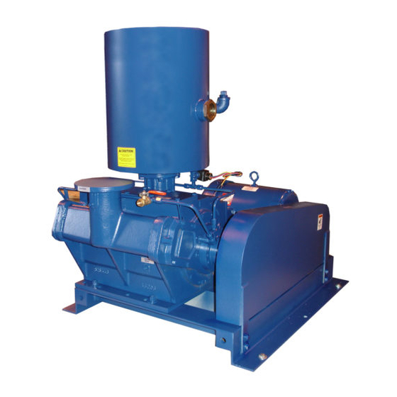
- Page 1 KINNEY ® Single-stage Rotary Piston Vacuum Pumps Manual 1817 Rev A p/n 001817 0000 WARNING: Do Not Operate Before Reading Manual KDH Series OPERATOR’S MANUAL Models KDH-130 KDH-150 Tuthill Vacuum & Blower Systems tuthillvacuumblower.com 800.825.6937...
- Page 2 WARNING CAUTION DO NOT VALVE OR RESTRICT PUMP DISCHARGE OPENING. USE OIL MIST ELIMINATOR WHEN OPERATING PUMP, ENSURE ADEQUATE VENTILATION WHEN DISCHARGING INDOORS DO NOT OPERATE REFER TO MANUAL SAFETY INSTRUCTIONS. WITHOUT BELT GUARD NOTICE The above safety instruction tags were permanently affixed to your pump prior to shipment. Do not remove, paint over or obscure in any manner.
-
Page 3: Table Of Contents
TABLE OF CONTENTS PAGE INTRODUCTION Replacing KDH-130 with KDH 130B DESCRIPTION Operating Mechanism Inlet & Outlet Valves Sealing and Lubrication Sealing Oils Operating Cycle Gas Ballast Dynamically Balanced Pump INSTALLATION Mounting the Pump Connecting Cooling Water Vacuum Piping Oil Separator Piping Electrical Connections Prestart Checks OPERATION... -
Page 4: Introduction
INTRODUCTION GENERAL This manual applies to KDH-130, and KDH-150 pumps built from 1974 to date. Earlier models may differ. The KDH-130 was replaced by the KDH-130B (and by the KDH-131 for radiator filling applications) in November 1987. Serial numbers between 871080 and on are the new “B” model. The differences between the KDH-130 and the KDH- 130B are: 1. -
Page 5: Inlet & Outlet Valves
Within each section is a piston which is driven by a cam. The cams are mounted 180 degrees apart on a single shaft so that the centrifugal forces of the moving pistons will oppose one another. The shaft passes through the center wall separating the two pump sections and is supported in bearings in the heads at each end of the cylinder. -
Page 6: Dynamically Balanced Pump
DYNAMICALLY BALANCED PUMP The term “dynamically balanced” applies to pumps which have been specifically balanced to reduce vibration. The KDH series are dynamically balanced by having each cam a different weight and adding counterweight to the pump sheave. The heavier cam is installed on the open head or drive shaft end of the pump. When reassembling a pump or ordering parts, be careful to distinguish between the heavy or open head cam and the light or closed head cam. -
Page 7: Operation
1. Be sure that the suction lines are absolutely free of foreign matter and perfectly tight. Use an inlet protection screen or drop out trap on new installations or where large welded piping is employed. 2. Make sure that the pump discharge is not obstructed 3. -
Page 8: Gas Ballast
The gas ballast valve is a manual valve located on top of the pump between the suciton flange and the drive end. A pipe connects it to both ends of the pump. Oil sealed mechanical vacuum pumps can become contaminated by vapors (commonly water or solvents) which have condensed and mixed with the oil. -
Page 9: Overheating Of Coils
Coils are designed to operate with about 50°F temperature rise. Since coils are furnished to hold the valve open they should not exceed this temperature in normal operation. Hot smell or smoke calls for investigation. First check for valve not opening due to low voltage. Failure of the valve to open when energized will cause overheating. STICKING AND JAMMING Foreign matter may cause the valve to stick, jam or leak. -
Page 10: Leak Checking Techniques
Check the lowest pressure attainable when each segment is added. If the pressure is close to that obtained previously, add the next segment. If the pressure is not, leak test the last segment. When leak checking process chambers, start at the air and gas inlet valves, doors, sight ports, electrical and mechanical feed-throughs, gauge tube fittings and any other penetrations into the vacuum portion of the process equipment. -
Page 11: Solenoid Valve
permanent repairs with Loctite 515. If gasketed connections are suspected, remake the connections. (Plastic sealing compound may be used to make temporary gaskets; theses should not be made too thickly since the material may be squeezed into the pump.) Check carefully around the head to cylinder joints, securing bolts, oil lines, plugs, and generally any penetration into the vacuum pumping portion of the pump. -
Page 12: Mechanical Shaft Seal
springs into three pairs, aligning the guide tabs in each pair. 2. Slide the first pair of springs on to the lift stop with the guide tab first. That is, with the guide tab retaining groove between each spring pair so that the springs are spaced equally around the valve. 3. -
Page 13: Maintenance
OVERHAUL GENERAL Arrangements for repair service can be made with Tuthill Vacuum & Blower Systems to either repair pumps on site or return them to the manufacturer for repair. Call Tuthill Vacuum & Blower Systems at (800) 525-6937 for service locations or for the proper procedure to return a pump back to the factory for repair. -
Page 14: Assembly
2. Remove oil and gas ballast lines. 3. Remove CE (closed end) cap and CE head. 4. With the cam and piston towards the bottom of the cylinder bore, remove the piston and slide pin. 5. Remove clamping plate, locknut and shaft seal housing. 6. -
Page 15: Replacement Parts
REPLACEMENT PARTS SPARE PARTS A minimum quantity of spare parts can save costly and perhaps lengthy periods of breakdown. Tuthill Vacuum & Blower Systems offers different levels of maintenance kits for servicing of the pumps. Contact the factory at 1-800-825-6937 with the serial number for more information. - Page 16 KDH-130B & 150 FINAL ASSEMBLY...
- Page 17 KDH-130B & 150 FINAL ASSEMBLY ITEM # DESCRIPTION PART NUMBER CYLINDER 808556 D000 HEAD, OE & CE 808554 D000 CAP, CLOSED END 808563 B000 HOUSING, SS & BRG 808557 B000 BOTTOM PLATE 808568 B000 SIDE COVER 808567 A000 COVER, VLV CHMBR 807051 B000 CAM, OE 801324 B000...
-
Page 18: Warranty
WARRANTY – VACUUM PRODUCTS Subject to the terms and conditions hereinafter set forth and set forth in General Terms of Sale, Tuthill Vacuum & Blower Systems (the Seller) warrants products and parts of its manufacture, when shipped, and its work (including installation and start-up) when performed, will be of good quality and will be free from defects in material and workmanship. - Page 19 NOTES: IMPORTANT All blowers manufactured by Tuthill Vacuum & Blower Systems are date coded at time of shipment. In order to assure you of the full benefits of the product warranty, please complete, tear out and return the product registration card, or register online at tuthillvacuumblower.com.
- Page 20 For Service & Repair, Technical Support, or Product Sales contact: VACUUM & BLOWER SYSTEMS Tuthill Vacuum & Blower Systems TUTHILL CORPORATION 4840 West Kearney Street Springfield, Missouri USA 65803-8702 O 417.865.8715 800.825.6937 F 417.865.2950 Manual 1817 Rev A p/n 001817 0000 tuthillvacuumblower.com...
Need help?
Do you have a question about the KINNEY KDH Series and is the answer not in the manual?
Questions and answers