Table of Contents
Advertisement
WARNING: Do Not Operate Before Reading Manual
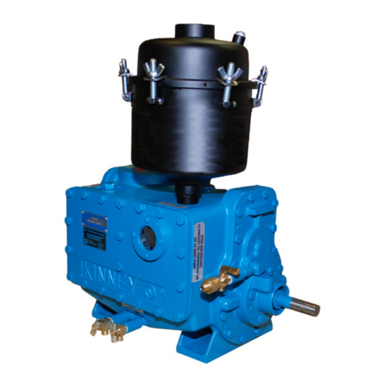
KC Series
OPERATOR'S MANUAL
Models
KC-5
KC-8
All rights reserved. Product information and specifications subject to change.
Tuthill Vacuum & Blower Systems
KC-15
Copyright © 2017 Tuthill Vacuum & Blower Systems
KINNEY
®
Two-Stage, Rotary Piston Vacuum Pump
Manual 1807 Rev B p/n 001807 0000
tuthillvacuumblower.com
800.825.6937
Advertisement
Table of Contents

Related Manuals for Tuthill KINNEY KC Series


Summary of Contents for Tuthill KINNEY KC Series
- Page 1 WARNING: Do Not Operate Before Reading Manual KC Series OPERATOR’S MANUAL Models KC-5 KC-15 KC-8 Copyright © 2017 Tuthill Vacuum & Blower Systems All rights reserved. Product information and specifications subject to change. Tuthill Vacuum & Blower Systems tuthillvacuumblower.com 800.825.6937...
- Page 2 The employees of Tuthill Vacuum & Blower Systems thank you for your purchase! Tuthill Vacuum & Blower Systems proudly manufactures A company with heart Kinney vacuum pumps and M-D Pneumatics blowers and right from the start. ® vacuum boosters in Springfield, Missouri, USA. We bring 100+ years of engineering experience and solid, hands- on care to help customers keep their processes running.
-
Page 3: Table Of Contents
Table of Contents Table of Contents Introduction .................. 1 Description .................... 1 Pump Components ................2 Operating Cycle ................. 2 Sealing and Lubrication ............. 3 Oil Types ..................3 Specifications ..................4 Safety .................... 5 Graphic Conventions Used in this Manual ..........5 Safety Instruction Tags ................ - Page 4 Table of Contents Pre-Start Checks ................. 10 Operation ..................11 Starting the Pump ................12 Stopping the Pump ................12 Gas Ballast ..................12 Special Refrigeration Service Pumps ..........13 Maintenance ................14 Periodic Maintenance ................. 14 Changing the Oil ................. 14 Flooding ....................
- Page 5 Table of Contents KC-8C Exploded View Drawing ..........32 KC-8C Parts List ............... 33 KC-15D Exploded View Drawing ..........34 KC-15D Parts List ..............35 KC-15L Exploded View Drawing ..........36 KC-15L Parts List ..............37 Manual 1807 Rev B p/n 001807 0000...
-
Page 6: Manual 1807 Rev B P/N 001807
Table of Contents Manual 1807 Rev B p/n 001807 0000... -
Page 7: Introduction
DESCRIPTION CONGRATULATIONS on the purchase of a new KINNEY® KC™ Two-stage, Rotary Piston Vacuum Pump from Tuthill Vacuum & Blower Systems. The KC series of compound high vacuum pumps Please examine the pump for shipping damage, covered by this manual consists of two basic pump... -
Page 8: Pump Components
Introduction separator. This combination oil separator and oil it is compressed and discharged into the cored mist eliminator thoroughly filters the pump exhaust passageway that leads to the inlet of the backing and results in a cleaner pump area, without stage. -
Page 9: Sealing And Lubrication
(one be used. Tuthill Vacuum & Blower Systems can at the discharge of each stage), through internal recommend fluids to fit most special applications. -
Page 10: Specifications
Introduction SPECIFICATIONS MNDTL KC-5 KC-8 KC-15 5 CFM 8 CFM 15 CFM Free air displacement (1.42 L/sec) (3.78 L/sec) (7.08 L/sec) Pump speed 630 rpm 1,000 rpm 525 rpm 0.33 HP 0.5 HP 1.0 HP Motor (0.25 kW) (0.37 kW) (0.75 kW) 0.5 qt 0.8 qt... -
Page 11: Safety
SAFETY GRAPHIC CONVENTIONS USED IN NOTE: Indicates a procedure, practice, or condition that should be followed in THIS MANUAL order for the equipment to function in the manner intended. The following hazard levels are referenced within this manual: SAFETY INSTRUCTION TAGS DANGER WARNING Indicates a hazardous situation that, if not... -
Page 12: Safety Precautions For Rotary Piston Pumps
Safety SAFETY PRECAUTIONS FOR • Do not restrict the pump discharge in any way or place valves in the discharge line. The vacuum ROTARY PISTON PUMPS pump is a compressor and will generate high pressures without stalling the motor when operated at low suction pressures. -
Page 13: Installation
Use manifolding tighten or under-tighten the drive. A general rule that is no smaller than the pump inlet. Tuthill for correct V-belt tension is to tighten the drive just recommends arranging the inlet manifolding to enough to prevent slippage when operating at full prevent oil migration back into the system. - Page 14 Tuthill Vacuum & Blower manifold is very close to the pressure obtained with Systems. Other types of connectors may be too the pump inlet blanked off.
-
Page 15: Vacuum Gauges
Installation ELECTRICAL CONNECTIONS If threaded connections are used, clean the threads and turn them together about two turns. Cover the remaining exposed threads with a sealing compound such as Loctite 567 or PTFE WARNING tape for piping up to 1 in. (25.4 mm) in diameter. Use Titeseal on large pipe sizes. -
Page 16: Filling The Pump With Oil
Installation system pressure should be close to that obtained 2. Check that the pump has been filled with oil. with the pump inlet closed off. 3. Check that the pump can be turned over by hand without mechanical interference. The inlet should be open to atmospheric pressure, and FILLING THE PUMP WITH OIL additional turning force is required when the... -
Page 17: Operation
OPERATION Figure 4-1 – Pump Components Manual 1807 Rev B p/n 001807 0000... -
Page 18: Starting The Pump
Operation STARTING THE PUMP 2. Vent the pump suction to atmospheric pressure by opening a vent valve. Turn off the power to the pump motor. Perform the pre-start checks as described in Pre‑Start Checks on page 10. NOTE: If the system does not have a pump isolation valve, vent the system to NOTE: Ohe minimum starting temperature is 50°F... -
Page 19: Special Refrigeration Service Pumps
Operation SPECIAL REFRIGERATION SERVICE To use the gas ballast technique, proceed as follows: PUMPS • Continuous gas ballast: With the pump operating, open the gas ballast valve until the Kinney offers high vacuum pumps that are ultimate pressure is slightly below that needed specifically engineered for servicing refrigeration for the process. -
Page 20: Maintenance
MAINTENANCE PERIODIC MAINTENANCE CHANGING THE OIL Check the oil level daily for the first week of All moisture, as well as other vapors present in the operation and weekly thereafter. The oil level system, will be drawn into the pump. Some may be should be about midway on the sight gauge when condensed and will collect in the backing stage oil operating at low inlet pressures. -
Page 21: Flooding
Maintenance FLOODING The oil separator-mist eliminator assembly can flood if the pump is operated for prolonged periods higher than 5 Torr (6.7 mbar a). This oil buildup will If the pump is not vented to atmosphere when cause oil droplets to be discharged when the pump stopped under vacuum, it is possible for oil to flood is operating. - Page 22 Maintenance Figure 5-1 – Oil Return Line Manual 1807 Rev B p/n 001807 0000...
-
Page 23: Stalling
Maintenance Associated Virtual Leaks* Process Leaks Equipment System not Operating Pressure not Attainable Operator Error Vacuum Contamination Pump Leaks Malfunctions * Pressure rises due to internal causes such as contamination by high vapor pressure materials outgassing from associated equipment work, and leaking from trapped volumes of air. Figure 5-2 –... -
Page 24: Troubleshooting
TROUBLESHOOTING Although KINNEY® KC™ rotary piston vacuum pumps are well designed and manufactured, problems may occur due to normal wear and the need for readjustment. The following chart lists symptoms that may occur along with probable causes and remedies. SYMPTOM PROBABLE CAUSE REMEDIES Faulty process... -
Page 25: Checking Pump Performance
Troubleshooting SYMPTOM PROBABLE CAUSE REMEDIES Electrical power loss Check power at the pump. Pump malfunctioning See Stalling on page 17. See V-Belt on page 7 Contaminated pump Pump stalls and Changing the Oil on page 14. oil or insufficient lubrication Blocked pump Clear the pump discharge line. -
Page 26: Pump Leaks
Troubleshooting 3. Operate the pump for about 15 minutes until pumping portion of the pump. Check the shaft seal the lowest pressure is reached. Note the for mechanical defects, such as a cracked carbon reading obtained. washer or hardened rubber components. The reading obtained should be between the pump’s specification blank-off pressure (low end) CHECKING PROCESS EQUIPMENT... -
Page 27: Leak Checking Techniques
Troubleshooting LEAK CHECKING TECHNIQUES may be contaminated by vapors yet not change color. If a leak detector is not available, cover suspected leaks with a low-vapor pressure sealing compound, DISCHARGE VALVE such as Apiezon Q, Duct Seal, or Plasticine ® ®... -
Page 28: Shaft Seal
Troubleshooting discharge holes. Clean this from the valve 4. Remove the rotating portion of the shaft seal and check that the holes are not worn into the from the shaft. This may require a heavy pull, valves. especially if the unit has heat bonded to the shaft. - Page 29 Troubleshooting 13. Replace the pump drive key and pulley. Replace the V-belt drive and tension it as described in Mounting on page 7. Replace the belt guard. Test the pump per Checking Pump Performance on page 19. Figure 6-3 – Shaft Seal Assembly Manual 1807 Rev B p/n 001807 0000...
-
Page 30: Disassembly
DISASSEMBLY Although these instructions describe complete heavy pull, especially if the unit has heat disassembly, disassemble the pump only to the bonded to the shaft. In extreme cases, extent necessary to repair it. it may be necessary to remove the open head or shaft seal housing to remove the These instructions make reference to the open seal. - Page 31 Disassembly 14. Remove the closed head by unscrewing the closed head securing cap screws and breaking the seal between the closed head and the cylinder. 15. Remove the closed head piston and slide pin. Note how they were removed so that they may be later reassembled in the same position.
-
Page 32: Reassembly
Carefully apply a thin coat of evaporate them by vapor degreasing or washing Loctite 515 to the sealing faces of the cylinder in acetone or alcohol. Tuthill Vacuum & Blower and the head. Systems recommends a general cleaning solvent with flash point exceeding 140°F (60°C), such as... - Page 33 Reassembly On KC-15 models, position the open head washer. Be careful not to damage the seal slide pin with the inlet ports in the piston slide face or cut the rubber. Remove the cover facing away from the discharge side of the from the shaft.
- Page 34 Reassembly Manual 1807 Rev B p/n 001807 0000...
-
Page 35: Replacement Parts
REPLACEMENT PARTS The following drawings and parts lists cover all the parts in each model. Any of these parts may be ordered from Tuthill for replacement as necessary. SPARE PARTS Recommended spare parts are indicated on the parts lists by an asterisk preceding the description of the item. -
Page 36: Exploded Views And Parts Lists
Replacement Parts EXPLODED VIEWS AND PARTS LISTS KC-5 and KC-8 Exploded View Drawing KC-5 KC-8 Pump RPM 1022 Motor HP (kW) 0.33 (0.25) 0.50 (0.37) Oil Capacity, qts. (liters) 0.8 (0.76) Forced Drain w/ open suction, qts. (liters) 0.85 (0.80) Use Loctite 515 vacuum pump sealant for assembly. -
Page 37: Kc-5 And Kc-8 Parts List
Replacement Parts KC-5 and KC-8 Parts List ITEM NO. DESCRIPTION ITEM NO. DESCRIPTION SHAFT SEAL CYLINDER RETAINING RING HEAD, OPEN END HEAD, CLOSED END HOUSING, SHAFT SEAL GAS BALLAST VALVE CAP, CLOSED END DRAIN COCK W/ SEAL COVER, CYLINDER GASKET CAM, OPEN END (HEAVY) CAP SCREW, HEX HEAD CAM, CLOSED END... -
Page 38: Kc-8C Exploded View Drawing
Replacement Parts KC-8C Exploded View Drawing Free Air Displacement , CFM (L/sec) 8 (3.78) Pump Rotative Speed, RPM 1022 Ultimate Pressure, Torr (mbar a) .005 (.007) Motor HP (kW) 0.75 (0.56) Oil Capacity, qts. (liters) 0.8 (0.76) Use Loctite 515 vacuum pump sealant for assembly. For best performance, use only AX vacuum pump oil. -
Page 39: Kc-8C Parts List
Replacement Parts KC-8C Parts List BRAKE BRAKE ITEM FLUID REFRIGERATION/ ITEM FLUID REFRIGERATION/ DESCRIPTION DESCRIPTION SERVICE MINERAL OIL QTY SERVICE MINERAL OIL QTY SHAFT SEAL CYLINDER RETAINING RING HEAD, OPEN END KEY, CAM HEAD, CLOSED KEY, DRIVE SHAFT HOUSING, SHAFT DRAIN COCK W/ SEAL SEAL... -
Page 40: Kc-15D Exploded View Drawing
Replacement Parts KC-15D Exploded View Drawing Free Air Displacement , CFM (L/sec) 15 (7.08) Pump Rotative Speed, RPM Ultimate Pressure, Torr (mbar a) .005 (.007) Motor HP (kW) 1 (0.75) Oil Capacity, qts. (liters) 3.0 (2.84) After normal oil drain, start pump to force out residual oil. Then, refill both stages with quantities shown above. Use Loctite 515 vacuum pump sealant for assembly. -
Page 41: Kc-15D Parts List
Replacement Parts KC-15D Parts List BRAKE BRAKE ITEM FLUID REFRIGERATION/ ITEM FLUID REFRIGERATION/ DESCRIPTION DESCRIPTION SERVICE MINERAL OIL QTY SERVICE MINERAL OIL QTY PIPE PLUG CYLINDER SEAL WASHER HEAD, OPEN END CAP SCREW, HEX HEAD, CLOSED HEAD DOWEL PIN HOUSING, SHAFT SEAL CAP SCREW, HEX HEAD... -
Page 42: Kc-15L Exploded View Drawing
Replacement Parts KC-15L Exploded View Drawing Free Air Displacement , CFM (L/sec) 15 (7.08) Pump Rotative Speed, RPM Ultimate Pressure, Torr (mbar a) .005 (.007) Motor HP (kW) 1 (0.75) Oil Capacity, qts. (liters) 3.0 (2.84) After normal oil drain, start pump to force out residual oil. Then, refill both stages with quantities shown above. Use Loctite 515 vacuum pump sealant for assembly. -
Page 43: Kc-15L Parts List
Replacement Parts KC-15L Parts List BRAKE BRAKE ITEM FLUID REFRIGERATION/ ITEM FLUID REFRIGERATION/ DESCRIPTION DESCRIPTION SERVICE MINERAL OIL QTY SERVICE MINERAL OIL QTY PIPE PLUG CYLINDER SEAL WASHER HEAD, OPEN END CAP SCREW, HEX HEAD, CLOSED HEAD DOWEL PIN HOUSING, SHAFT SEAL CAP SCREW, HEX HEAD... - Page 46 WARRANTY – VACUUM PRODUCTS Subject to the terms and conditions hereinafter set forth and set forth in General Terms of Sale, Tuthill Vacuum & Blower Systems (the Seller) warrants products and parts of its manufacture, when shipped, and its work (including installation and start-up) when performed, will be of good quality and will be free from defects in material and workmanship.
- Page 47 NOTES: IMPORTANT All blowers manufactured by Tuthill Vacuum & Blower Systems are date-coded at time of shipment. In order to assure you of the full benefits of the product warranty, please complete, tear out and return the product registration card, or register online at tuthillvacuumblower.com.
- Page 48 4840 West Kearney Street Springfield, Missouri USA 65803-8702 O 417.865.8715 800.825.6937 F 417.865.2950 Manual 1807 Rev B p/n 001807 0000 tuthillvacuumblower.com 1/18 Copyright © 2017 Tuthill Vacuum & Blower Systems All rights reserved. Product information and specifications subject to change.
Need help?
Do you have a question about the KINNEY KC Series and is the answer not in the manual?
Questions and answers