Midea SBS Series Service Manual
Hide thumbs
Also See for SBS Series:
- Service manual (72 pages) ,
- Service manual (56 pages) ,
- Service manual (59 pages)
Table of Contents
Advertisement
Quick Links
Service Manual
The picture in this service manual is only for reference, and specific appearance
and configuration are subject to the real product.
This manual mainly teaches the method, the specific work skill needs engineer to
accumulate through the daily work.
There are special components used in this equipment which are important for safety. These parts are marked
by
in the Schematic Diagrams, Circuit Board Diagrams, Exploded Views and Replacement Parts List. It is
essential that these critical parts should be replaced with manufacturer's specified parts to prevent shock, fire
or other hazards. Do not modify the original design without permission of manufacturer.
WARNING
Important Safety Notice
1
Service Manual_2018-V2.0
SBSSERIES
Advertisement
Table of Contents

Related Manuals for Midea SBS Series


Summary of Contents for Midea SBS Series
- Page 1 Service Manual_2018-V2.0 Service Manual SBSSERIES The picture in this service manual is only for reference, and specific appearance and configuration are subject to the real product. This manual mainly teaches the method, the specific work skill needs engineer to accumulate through the daily work. WARNING Important Safety Notice There are special components used in this equipment which are important for safety.
- Page 2 Manufacturers or distributors are not responsible for the content of the Manual and interpretation thereof. Midea Refrigerators Technical Maintenance Manual Copyright @2017 All rights reserved. Replication of all or part of the Manual in any forms shall not be allowed without written approval by the Overseas Sales Corporation of Midea Refrigerators.
-
Page 3: Table Of Contents
Service Manual_2018-V2.0 Contents 重要更新说明 SIGNIFICANT UPDATE NOTES(NONE) ................6 2. 安全警示规范 SAFETY WARNING CODE ..................... 7 2.1 作业安全警告 W ..................7 ARNING FOR OPERATION SAFETY 2.2 冷媒安全须知 S ................9 AFETY INSTRUCTION FOR REFRIGERANT 3. 运输 TRANSPORT ............................10 3.1 搬运 H ............................ - Page 4 Service Manual_2018-V2.0 6.1 电气参数 E ......................21 LECTRICAL PARAMETERS 6.2 制冷温度设置范围 C ..............22 OOLING TEMPERATURE SETTING RANGE 6.3 除霜部件 D ........................22 EFROSTING PARTS 6.4 电路图 C .......................... 22 IRCUIT DIAGRAM 6.5 主控板结构图 M ................ 23 AIN CONTROL BOARDSTRUCTURE DIAGRAM 6.6 电磁阀...
- Page 5 Service Manual_2018-V2.0 8.10 吧台 B (N ) ........................ 39 AR COUNTER 8.11 饮水机 W (N ) ...................... 39 ATER DISPENSER 8.12 制冰机 I (N ) ........................39 CE MAKER 8.13 水过滤器 (N ) ..................39 WATER FILTER COMPONENT 9.感温系统 TEMPERATURE SENSING SYSTEM ................... 40 9.1 传感器的位置...
-
Page 6: 重要更新说明 Significant Update Notes(None)
Service Manual_2018-V2.0 11.1 压缩机的开停控制规则 C .......... 50 OMPRESSOR ON AND OFF ONTROL SPECIFICATIONS 11.2 变频板故障分析 V ............. 50 ARIABLE FREQUENCY DRIVER BOARD FAULT ANALYSIS 12. 故障排除方法 TROUBLESHOOTING METHOD ..................51 12.1 不制冷(风冷电控式)N ) ............. 51 O COOLING IR COOLING LECTRONIC 12.2 压缩机不工作... -
Page 7: 安全警示规范 Safety Warning Code
Service Manual_2018-V2.0 2. Safety Warning Code 2.1 Warning for operation safety Important Safety Instructions CAUTION RISK OF ELECTRIC SHOCK DO NOT OPEN This symbol indicates that dangerous voltage constituting a risk of electric shock is present within your freezer. This symbol indicates that there are important operating and maintenance instructions in the literature accompanying your freezer. - Page 8 Service Manual_2018-V2.0 CONNECTING ELECTRICITY Electrical Shock Hazard. Failure to follow these instructions can Plug into a grounded 3-prong outlet. result in death, fire, or electrical shock. Do not remove the ground prong. Do not use an adapter. WARNING Electric Shock Hazard Failure to follow these instructions can result in electric shock, fire, or death.
-
Page 9: 冷媒安全须知 Safety Instruction For Refrigerant
Service Manual_2018-V2.0 13) Do not store or use gasoline or any flammable liquids inside or in the vicinity of this freezer. 14) Do not use extension cords or ungrounded (two-prong) adapters with this freezer. If the power cord is too short, have a qualified electrician install an outlet near the freezer. Use of an extension cord can negatively affect the freezer’s performance. -
Page 10: 运输 Transport
Service Manual_2018-V2.0 3. Transport 3.1Handling Handling 1)Protect the refrigerator in moving it,Same as shown as left photo, please move it by handcart with cushion 2)Remove all packing materials and bottom cushion, the move into house for placement 3)After moving it to appropriate location, wait for 2 hours before power on. -
Page 11: 安装和调试 Installation And Commissioning
Service Manual_2018-V2.0 4. Installation and commissioning 4.1Door Disassembly and Assembly The refrigerator door needs to be dismantled if it cannot enter the room in the whole. Disassembly of Freezer door 1) As shown as right photos, use screwdriver to remove the 2 pcs screws, and then remove the upper hinge cover. - Page 12 Service Manual_2018-V2.0 1) Use screwdriver to remove the 2 pcs screws, and then remove the upper hinge cover. 2) Use cross screwdriver or socket spanner to remove the 2 pcs M5 screws and 1 pc grounding screw by anticlockwise, and then remove the upper hinge. Note: please make sure the refrigerator door fit closely to the cabinet;...
- Page 13 Service Manual_2018-V2.0 1) Put the freezer door down gently until the axis of hinge inserted into the axis hole of door completely. 2) Put the upper hinge on suitable position, then use cross screwdriver or socket spanner to fix the 2 pcs M5 screws by clockwise.
-
Page 14: 安装位置 Installation Location
Service Manual_2018-V2.0 2) Put the upper hinge on suitable position, then use cross screwdriver or socket spanner to fix the 2 pcs M5 screws and 1 pc grounding screw. 3) Put the hinge cover on suitable position, and then use the screwdriver to fix the 2 pcs screws. -
Page 15: 箱体调平 Leveling Of The Refrigerator
Service Manual_2018-V2.0 4.3Leveling of the refrigerator Leveling of the refrigerator If the refrigerator cannot be placed steadily, adjust the footing to level it. 4.4Left or right open door reversal (None) Door reversal Door reversal None 4.5Installation of handle (None) Installation of handle Installation of handle None 4.6Installation of door lock(None)... - Page 16 Service Manual_2018-V2.0 Use screwdriver to remove the 2 pcs screws, and then remove the upper hinge cover.Use screwdriver to loosen the 2 pcs screws,right and left adjust the upper hinge tomake door aperture be homogeneity.Put the hinge cover on suitable position, and then use the screwdriver to fix the 2 pcs screws.
- Page 17 Service Manual_2018-V2.0...
-
Page 18: 产品配置和尺寸 Productconfiguration And Dimension
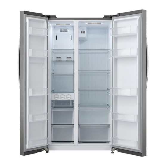
Service Manual_2018-V2.0 5. Productconfiguration and dimension 5.1 Main parts and their names (The picture is only for reference, and specific appearance and configuration are subject to the real product) Freezer chamber Refrigerator chamber ❶LED lighting ❺LED lighting ❷Glassshelf ❻Glassshelf ❸Door tray ❼Door tray ❹drawer ❽Box for keeping fruits and vegetables... - Page 19 Service Manual_2018-V2.0 Depth (Door open 135 deg. w) 1091 Width (Door open 135 deg. w) 1542 (The picture is only for reference)
-
Page 20: Ocation Of S/N
Service Manual_2018-V2.0 5.3Location of S/N Some products also have S/N on the lower part of the right side of the Cabinet. -
Page 21: 产品规格 Product Specification
Service Manual_2018-V2.0 6. Product specification 6.1Electrical parameters Applicable Models Product Name CE-BCD640WE-JT Product Code 22031050000701 Item Specification Specification Refrigerant R600a Compressor VFL110CY1H Starter(PTC) None Overload protector(OLP) B78-120 P A Integrate PTC+OLP None DBFC-CTCLM Variable frequency driver board /220-240V(50/60)Hz Capacitor None Power filter Have Power reactor... -
Page 22: Ooling Temperature Setting Range
Service Manual_2018-V2.0 6.2Cooling temperature setting range Compartment The highest ( Lowest ( Freezing Refrigerating 6.3Defrosting parts electronic type Item Specification Defrosting sensor NTC B3839 Fuse 73℃ Defrost heater in freezing chamber 230V 240W 6.4Circuit diagram F: Freezer; R: Refrigerator; FD: Freezer Defrost; C: Condensation ; A:ambient temperature... -
Page 23: 主控板结构图 Main Control Boardstructure Diagram
Service Manual_2018-V2.0 6.5Main control boardstructure diagram Number name Number name R-led F-led F-defrost sensor F-defrost heater F- sensor F-Fan R- sensor Frequency-conversion PCB R- door switch Damper F- door switch Display 6.6Electric exchange valve(None) Model Specification None 6.7Water valve(None) Model Specification None... - Page 24 Service Manual_2018-V2.0...
-
Page 25: Cooling Air
Service Manual_2018-V2.0 7.Refrigerating piping system and circulating route of cooling air 7.1 Refrigerating piping system ❶Compressor→❷Condenser→❸Anti-water condensed pipe→❹Drier→❺Capillary Tube→❻Evaporator→❼Suction Pipe→❽Suction connection Pipe→❶Compressor 7.2Special soldering position (None) -
Page 26: Irculating Route Of Cooling Air
Service Manual_2018-V2.0 7.3Circulating route of cooling air... -
Page 27: 部件拆装 Dismantling Of Parts
Service Manual_2018-V2.0 8. Dismantling of parts 8.1 Parts on the door Door seal Door seal is installed into door liner groove. 1)Open the refrigerator door; 2)Take the door seal ① out of door liner; Door tray While squeezing it inward, lift up the baffle and take it out from refrigerator liner. -
Page 28: Ight System
Service Manual_2018-V2.0 The drawer is located at the freezing chambers; 1)Pull the drawer out completely; 2)Lift it up slightly and take it out from the refrigerator. 8.3 Light system Light Light of the refrigerating 1)Turn over the lampshade hard with your hands or two flat-blade screwdrivers at two grooves marked with red circles shown in the picture and take it down 2)Push away the hook with your hand along the arrow... -
Page 29: Ir Duct Components Refrigerating Chamberand Fan Motor
Service Manual_2018-V2.0 1)As shown in the picture, loosen by screwdriver 2 fixing screws of the hinge cover and take it down 2)Press the snap joint in the circle and push it outward along the arrow direction. Complete the disassembly of door light switch. -
Page 30: Ir Duct Components In Freezing Chamber And Fan Motor
Service Manual_2018-V2.0 3)Catch hold of air duct foam in refrigerating chamber and pull it towards the right along the arrow direction shown in the picture until air duct foam is separated from refrigerator body, remove connecting terminals of ventilation door and take out refrigerating air duct foam. Fan motor of air duct None Electric damper... -
Page 31: Vaporator And Efrost System
Service Manual_2018-V2.0 4)Evaporator cover ahead of freezing chamber After the removal of upper air duct in freezing chamber. Catch hold of cover plate of freezing lower air duct shown in the picture, pull it out along the arrow direction until it is separated from refrigerator body and take it out. - Page 32 Service Manual_2018-V2.0 Components on the evaporator Defrost thermostat None Defrosting fuse① 1)Disconnect the fuse connector. 2)Cut off the band which fixes the fuse. 3)Separate the fuse and the evaporator. *Don’t break the welding of the evaporator in case that only the fuse needs to be replaced. Defrost sensor②...
-
Page 33: Ompressor Case
Service Manual_2018-V2.0 Defrosting fuse None Defrost sensor None Defrost heater None 8.7 Compressor case Rear cover 1)Remove by cross screwdriver the screws fixing back cover plate of compressor chamber anticlockwise 2)Take the back cover plate of compressor chamber upward. Compressor and the cooling system pipe 1)... - Page 34 Service Manual_2018-V2.0 4-1)Remove the screws(for some models) -Two screws outside -One screw inside 4-2)Remove the metal clamp(for some models) -Disassembly the metal clamp that is fix the electric appliance shield 5)Remove the clipping strip Slowly pull it out 6)Remove the protective cover -Pry the protective cover slowly from the upper part, -Pull it out and remove it.
- Page 35 Service Manual_2018-V2.0 7)Remove the starter and protector Unplug the starter and protector (you can use a screwdriver to pry it slowly) 8)Loosen the screw of the compressor bottom plate,remove the floor together with the compressor from the box. 9)Use the wrench to remove the bolts by steps❹❺❻❼, replace the compressor and reverse process can complete installation.
- Page 36 Service Manual_2018-V2.0 11)Replace the compressorand welding the compressor pipeline.-❿Welding the process pipeline.-⓫Welding the low-pressure muffler.-⓬Welding the high-pressure exhaust pipe. 12)Replace thefilter, Cu-Fe tubes welding ⓭used Ag welding rod, Cu-Cu tubes welding ⓮ used Cu welding rod. 13)Vacuum system,The degree of vacuum below 6Pa. 14)Perfusion refrigerant.
- Page 37 Service Manual_2018-V2.0 Back hanging wire tube condensor None Piping system in the compressor case 1. Compressor 6. Filter 2. Compresssor suction pipe 7. Suction pipe 3. Transition tube 8. Capillary 4. Left condenser 9. Right condenser 5. Anti-water condensation pipe Drain tray 1)Remove the bottom screws of the compressor bottom plate...
-
Page 38: 显控板 Display Control Board
Service Manual_2018-V2.0 2 ) Replace the drain tray, the reverse process can complete installation. 8.8 Display control board Display control board 1)Use vacuum cap to pull the control panel outwards 2) Disconnect the fast connector, then remove the control 8.9 Main control board Have variable frequency driver board 1) remove the screw anticlockwise,then remove the PCB housing cover... -
Page 39: Ar Counter One
Service Manual_2018-V2.0 2)Pull the lock of fast connector upwards,then disconnect the fast connector 3)Remove the screw anticlockwise,then remove the PCB and variable frequency driver board. 8.10 Bar counter(None) 8.11 Water dispenser(None) 8.12Ice maker(None) 8.13water filter component(None)... -
Page 40: 感温系统 Temperature Sensing System
Service Manual_2018-V2.0 9.temperature sensing system 9.1 Position of sensors Position of sensors Have 4 sensors ① Sensor in freezing chamber ② Sensor in refrigerating chamber ③ Defrost sensor freezing chamber ④ Ambient temperature sensor 9.2 Replacement of sensors Sensor in freezing chamber 1)To remove the air duct cover, remove thermal sponge 2)Take the sensor out from card slot;... -
Page 41: 传感器的更换 Sensor Replacement
Service Manual_2018-V2.0 Sensor in refrigerating chamber Refer to the method of disassembling the freezer compartment sensor. Ambient temperature and humidity sensor Defrost sensor in freezing chamber The defrost sensor is located on top of the evaporator. 1)Disconnect the connector of defrost sensor 2)Cut off the band which fixes the sensor. -
Page 42: Ensor Resistance (R/T)
Take out a new sensor to cut the head of sensor. (Spare parts code:11201007000795) Its technical specifications apply to all MIDEA refrigerators. Strip off the head of the sensor and connect it. Wrap the two wires together with insulation tape. - Page 43 Service Manual_2018-V2.0 20.01 8.841 4.167 2.094 1.115 18.9 8.392 3.972 2.005 1.071 17.87 7.968 3.788 1.919 1.029 16.9 7.568 3.613 1.838 0.9885 15.98 7.19 3.447 1.761 0.9506 15.12 6.833 3.29 1.687 0.914...
-
Page 44: 功能和操作 Function And Operation
Service Manual_2018-V2.0 10. Function and operation 10.1 Operation panel Icons Button AFRZ.TEMP. ① refrigerator icon BREF.TEMP. ② off icon CMODE ③ display zone of temperature DVACATION ④ Quick cooling by freezing ELOCK/UNLOCK ⑤ freezer icon ⑥ Unlock ⑦ vacation icon ⑧... -
Page 45: Isplay
Service Manual_2018-V2.0 10.2 Display At the first time of power-on, the display screen (including button light) will be bright for 3 seconds and then press the middle gear to show operation Normal operation displayWhen failure occurs, the corresponding LED light group will display fault code (circular display);... -
Page 46: Ontrol Of Ice Maker One
4) When display “3”, the ice maker will turn over the ice for twice, then intake water. 10.6Control of ice maker(None) 10.7Fault code and solutions Note: midea full common fault code, combined with the actual product display reference. Fault code Fault content... - Page 47 Service Manual_2018-V2.0 Step 3: Replace main control board Step 4: Replace electrical wiring main harness Step 1: Check whether the terminal of defrost sensor in main control board is welll stuck, pull out the terminal and re-stick it in place Step 2: Check to see if there’re foreign matters on the terminal.
-
Page 48: Efrosting Function
Service Manual_2018-V2.0 Step 1: Check whether the terminal ice maker sensor of main control Circuit fault of ice board is well stuck, pull out the terminal and re-stick it in place and maker sensor check if there is any foreign matter on the terminal Step 2: Check whether the terminal of ice maker is well Step 1: Check whether the terminal ambient humidity sensor of main control board is well stuck, pull out the terminal and re-stick it in place... -
Page 49: Ackup Data For Power Fail
Service Manual_2018-V2.0 defrosting heater has been working for 3 minutes, In forced defrosting mode, if the temperature of defrosting sensor is then the refrigerator will exit the test mode and always lower than 12°C and the return to normal operation mode defrosting heater has been working for 1 hour, Select to... -
Page 50: 压缩机 Compressor
Service Manual_2018-V2.0 11. Compressor 11.1Compressor on and off Control specifications 1.1 When one of the following conditions is met, the compressor stops: 1) Tr ≤ Trt; 2) The compressor runs continuously for more than 3 hours (Stop 10 minutes); 1.2 When all the following conditions are met, the compressor starts up: 1) Tr ≥Trk;... -
Page 51: 故障排除方法 Troubleshooting Method
Service Manual_2018-V2.0 12. Troubleshooting Method 12.1 No cooling(Air cooling-Electronic) -
Page 52: O Working Of Compressor
Service Manual_2018-V2.0 12.2 No working of compressor 12.3 Inside frosting, no defrosting... -
Page 53: Nside Frosting , No Defrosting -Maintenance Guidelines
Service Manual_2018-V2.0 12.4 Inside frosting, no defrosting-Maintenance guidelines... -
Page 54: Ight Is Not On
Service Manual_2018-V2.0 12.5 Light is not on 12.6Fan failure 12.7Defective defrost circuit... -
Page 55: Oise
Service Manual_2018-V2.0 12.8Noise 12.9Air duct not operated(electronically) 12.10ice makernot make ice... -
Page 56: 维修零部件图示和明细 Figures And Details Of Repair Parts
Service Manual_2018-V2.0 13. Figures and details of repair parts See this section in the TSP. - Page 57 MIDEA appliances after sales website tsp.midea.com For more information about Midea appliances after sales, please visit the tsp.midea.com For more information about the service manual, please visit the For more information about the EV and SBOM, please visit the tsp.midea.com...
Need help?
Do you have a question about the SBS Series and is the answer not in the manual?
Questions and answers