Table of Contents
Advertisement
Quick Links
FLARM Technology Ltd
Hinterbergstrasse 15
CH-6330 Cham
Document Status
Published status
☐ Draft
☒ Released
☐ Canceled
Version Control
Ver.
Date
1.0
2020-11-10
POWERFLARM FUSION
INSTALLATION MANUAL
Summary of changes
Initial version
Confidentiality status
☐ Internal
☐ NDA
☒ Public
Date: 2020-11-10
Version: 1.0
Page: 1 of 38
Document Number:
FTD-077
Advertisement
Table of Contents

Related Manuals for FLARM POWERFLARM FUSION


Summary of Contents for FLARM POWERFLARM FUSION
- Page 1 Date: 2020-11-10 Version: 1.0 POWERFLARM FUSION Page: 1 of 38 INSTALLATION MANUAL FLARM Technology Ltd Document Number: Hinterbergstrasse 15 FTD-077 CH-6330 Cham Document Status Published status Confidentiality status ☐ Draft ☐ Internal ☒ Released ☐ NDA ☐ Canceled ☒ Public Version Control Ver.
-
Page 2: Table Of Contents
2.4.7 D-sub DE-9 – Power, Data, and Audio Connections ..17 2.4.8 Audio Out ..............18 2.4.9 FLARM and 1090 MHz Antenna Connectors ....19 2.4.10 GPS Antenna (SMC Connector) ........20 Antennas ................20 2.5.1 External Antennas ............ 20 2.5.2... - Page 3 Additional Information ..............27 Troubleshooting and Error Codes ..........27 Warranty Information and Terms of Use ........27 Replacing PowerFLARM Core with PowerFLARM Fusion ....27 Replacing Classic FLARM with PowerFLARM Fusion ....... 27 Conformity Declarations ............28 Maximum Antenna Gain ............29 Industry Canada Notice and Marking ..........
-
Page 4: General Overview
General Aviation, light aircraft, and UAVs. It has been designed to support self-separation for both VFR and IFR in applicable airspace classes. Aircraft with a FLARM system alert the pilots when on a collision course with another aircraft. Similar to TCAS/TAS, visual and aural warnings indicate that a collision is imminent, requiring the pilots to take action. - Page 5 FLARM devices available (usually with an integrated display), as well as FLARM systems integrated into other avionics (e.g. EFIS-systems). FLARM is approved by EASA and others for installation in certified aircraft and is recommended by many aviation authorities and organizations. The installation is normally a minor change and can be done by any competent maintenance organization.
-
Page 6: System Description
CH-6330 Cham System Description PowerFLARM Fusion is a modern FLARM device for installation in General Aviation aircraft. It is based on the latest PowerFLARM technology and features a novel web app called FLARM Hub. PowerFLARM Fusion has been designed for worldwide use and connects to a range of displays, including tablet apps via Wi-Fi or Bluetooth. -
Page 7: Definitions
(optional). An Electronic Flight Bag (EFB) or navigation app running on a mobile device (tablet or phone), connected through Wi-Fi or Bluetooth. A web browser running FLARM Hub on a computer or mobile device. Definitions 1.2.1 Abbreviations... -
Page 8: Terminology
Fusion should be connected to at least one FLARM Compatible display. A list of displays certified as FLARM Compatible, as well as alternative means of compliance, can be found in Appendix C. Displays certified as FLARM Compatible can also be found in the Product Selector under the category “Primary Displays”:... - Page 9 Fusion, are normally designed for only one of the frequency bands. The external AV-75 antenna is designed for worldwide use. Only antennas supplied by FLARM Technology should be used. In addition, other antennas as specified in Appendix B may be used as well. Inappropriate antennas, especially antennas without complete insulation, can damage devices and should not be used.
-
Page 10: Additional Documents, Data, And Information
Always make sure that you are using the latest document. Updates will be communicated to official FLARM dealers, in the FLARM blog, and the official FLARM newsletter. Sign up to the newsletter from the FLARM website to ensure that important communication is not missed:... -
Page 11: Installation
FLARM is not required by any Certification Specification. Thus, there is no (E)TSO for FLARM, nor is one required. The installation is normally a minor change and must adhere to the Certification Specification applicable to the aircraft in which it is installed. -
Page 12: Minor Change And Standard Change
VFR). Housing Mount PowerFLARM Fusion to a suitable mounting location. The orientation of the device is discretionary. Do not mount the device on the “hot” side (engine side) of the firewall. Common installation locations are behind the instrument panel or in the E&E compartment in larger aircraft. -
Page 13: Displays
A list of displays certified as FLARM Compatible, as well as alternative means of compliance, can be found in Appendix C. Displays certified as FLARM Compatible can also be found in the Product Selector under the category “Primary Displays”: https://flarm.com/products/powerflarm/product-selector/... -
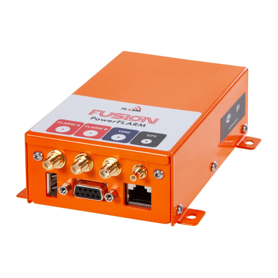
Page 14: Connections And Cabling
USB 2.0: Accepts USB flash drive for flight log readout, device update , and configuration. FLARM antennas A and B: When using a single antenna, connect to FLARM A. The internal FLARM antennas supplied with the device have a RED marking. -
Page 15: General Advice
The Fusion circuit breaker must be separate from other circuit breakers of essential systems. In flight, the pilots must be able to isolate FLARM from the aircraft's electrical system without interrupting the power supply to other essential avionics. -
Page 16: Display
Date: 2020-11-10 Version: 1.0 POWERFLARM FUSION Page: 16 of 38 INSTALLATION MANUAL FLARM Technology Ltd Document Number: Hinterbergstrasse 15 FTD-077 CH-6330 Cham 2.4.5 Display See Section 2.3 and Appendix C for display requirements. Use only high-quality shielded cables for the display connections. Up to 5 m cable length is normally acceptable. -
Page 17: D-Sub De-9 - Power, Data, And Audio Connections
Date: 2020-11-10 Version: 1.0 POWERFLARM FUSION Page: 17 of 38 INSTALLATION MANUAL FLARM Technology Ltd Document Number: Hinterbergstrasse 15 FTD-077 CH-6330 Cham 2.4.7 D-sub DE-9 – Power, Data, and Audio Connections Connecting power to an incorrect pin will burn the circuit boards, make the device unusable and void any warranty. -
Page 18: Audio Out
2.4.8 Audio Out PowerFLARM Fusion emits an intermittent 1 kHz waveform on Audio Out (Pin 1 on the D-sub connector) whenever a collision warning is issued. The frequency of the beep depends on the time to collision. In addition, a test beep is emitted during power-up if Audio out has been activated in the configuration. -
Page 19: Flarm And 1090 Mhz Antenna Connectors
2.4.9 FLARM and 1090 MHz Antenna Connectors FLARM A and B ports are reverse polarity female SMA connectors (RP-SMA) with a pin as center conductor. The 1090 port is a standard female SMA connector. Ensure that the antenna cable connectors are properly and fully screwed into the device. -
Page 20: Gps Antenna (Smc Connector)
Antennas The minimum number of antennas required for installation is one FLARM antenna and one GPS antenna. In addition, a second FLARM antenna should be installed for antenna diversity. The system can also optionally receive SSR transponder Mode-S and ADS-B 1090ES traffic on 1090 MHz using a separate 1090 antenna (recommended). - Page 21 (FLARM A) should have good view upwards and into the direction of flight and normally be placed on top of the aircraft. FLARM B (if installed) should be placed to complement the field of view of FLARM A, normally below the aircraft.
-
Page 22: Internal Antennas
Ensure that the antennas are not in contact with or close to any other object through which there might be an electrostatic discharge, e.g. the canopy. When two FLARM antennas are installed, ensure that they are at least 30 cm apart. In gliders where internal FLARM antennas may be used, ideal locations for the... -
Page 23: Usb Connector
Fusion. USB Connector PowerFLARM Fusion has a built-in USB A 2.0 connector for a USB flash drive. It can be used for PowerFLARM firmware updates, configuration, and readout of device information and flight recordings. The maximum supported size is 128 GB. -
Page 24: Firmware Updates
The expiry date shall never be relied upon for scheduling updates. The FLARM Hub firmware can be updated in FLARM Hub. This should normally be done whenever updating the PowerFLARM firmware but is not mandatory. Any compatibility constraints will be noted in the firmware release notes. -
Page 25: Annual Maintenance
FTD-077 CH-6330 Cham Annual Maintenance Each FLARM system must be inspected and updated every 12 calendar months. For installations in certified aircraft, the annual maintenance must be part of the Aircraft Maintenance Program (AMP) or equivalent. For other installations, the owner must set up an individual reminder 12 months after the previous maintenance. -
Page 26: Technical Specification
1 x 700 mA @ 5 V DC (D-sub, USB) D-sub DE-9 and RJ45 Data Ports RS-232 connection NMEA ICD @ 4.8-230 kBaud FLARM ICD: Wi-Fi (TCP, WebSocket) and Bluetooth Wireless Data GDL 90: Wi-Fi Audio Out AC, 1.7 V peak-to-peak @ 1 kΩ... -
Page 27: Additional Information
Appendix E. Replacing PowerFLARM Core with PowerFLARM Fusion The D-sub DE-9 and RJ45 connector pinouts on PowerFLARM Fusion are identical with PowerFLARM Core. In contrast to PowerFLARM Core, Fusion is available in only one version usable in all countries where FLARM operates. -
Page 28: Conformity Declarations
Firmware updates, IGC file downloads, and obstacle data uploads cannot be done via the data ports. Instead, they are done via FLARM Hub or with a USB flash drive. The USB extension cable should be installed in the instrument panel. -
Page 29: Maximum Antenna Gain
Date: 2020-11-10 Version: 1.0 POWERFLARM FUSION Page: 29 of 38 INSTALLATION MANUAL FLARM Technology Ltd Document Number: Hinterbergstrasse 15 FTD-077 CH-6330 Cham Maximum Antenna Gain Currently, the maximum antenna gain for external antennas is limited to 2.0 dBi for operation in the 902 MHz to 928 MHz band. The antenna gains must not exceed maximum EIRP limits set by the FCC/Industry Canada. -
Page 30: Appendix A - Mechanical Drawings
Date: 2020-11-10 Version: 1.0 POWERFLARM FUSION Page: 30 of 38 INSTALLATION MANUAL FLARM Technology Ltd Document Number: Hinterbergstrasse 15 FTD-077 CH-6330 Cham Appendix A – Mechanical Drawings... -
Page 31: Appendix B - Acceptable Antennas And Cables
If using other than supplied or listed antennas, it must be ensured that the antennas are acceptable for the applicable installation (e.g. environmental aspects) and radio frequency characteristics. Ensure that FLARM antennas have complete insulation and protection. The radio frequency characteristics may be verified by performing a range analysis. -
Page 32: Appendix C - Flarm Compatible Displays
This includes collision warnings, status information, error conditions, obstacle warnings, documentation, etc. If the primary display has not been certified as FLARM Compatible, it can continue to be used if the deviations are understood and the resulting risks are acceptable or mitigated. - Page 33 FTD-077 CH-6330 Cham The following FLARM displays have been certified as FLARM Compatible as of the date when this manual version was published. The approval is valid under the condition that the limitations listed below are adhered to. The approval is valid only for the latest display firmware/software that was released on the day this manual version was published, and any consecutive firmware/software versions.
-
Page 34: Appendix D - Installation Verification Checklist
Attachment installed parts. Installation basis A FLARM system that is installed is formally a change to the type certificate of the aircraft. The change is normally only a minor change and can be done as a Standard Change (CS-SC051 for ELA2 aircraft), or under an EASA Minor Change Approval (MCA) or the national equivalent. - Page 35 Product Selector under the category “Primary Displays”. If the primary display has not been certified as FLARM Compatible, it may be used if the deviations are understood and the resulting risks are acceptable or mitigated. See Appendix C for details.
- Page 36 If an error occurs, check the severity and type of error (error code) to determine the proper remedy. Verify that FLARM has GPS reception at the latest 15 minutes after power-on. The aircraft/device must be outside with a clear view of the sky. The system should indicate GPS and TX (Transmit).
-
Page 37: Appendix E - End User License Agreement (Eula)
"firmware", "license key", and "data" refer to such items Newsletter. installed or available in the FLARM device at time of purchase or 2.9. After power-up, FLARM performs a self-test which use, as applicable. - Page 38 (i) your first use of the FLARM device, your requirements or operate error free. software, firmware, license key, or data with actual 6.2.
Need help?
Do you have a question about the POWERFLARM FUSION and is the answer not in the manual?
Questions and answers